
L-section Matching Networks
Interactive Audio Lesson
Listen to a student-teacher conversation explaining the topic in a relatable way.
Introduction to L-section Networks
🔒 Unlock Audio Lesson
Sign up and enroll to listen to this audio lesson

Today, we're going to discuss L-section matching networks. These networks help us effectively match impedances, which is crucial for maximizing power transfer in RF circuits.

What exactly is meant by impedance matching, teacher?
Great question! Impedance matching ensures that the impedance of the source and load are equal, which minimizes signal reflections. Think of it as making sure all lights in a circuit have the same connection size to let the electricity flow smoothly.

So, can you tell me more about how L-section networks work?
Absolutely! An L-section network has an inductor and a capacitor. They can be arranged in series or parallel. The configuration affects how they match the impedances.

Can you give an example of when we would use a series versus a parallel arrangement?
Sure! A series configuration might be used if we need to match the load to the source impedance more closely, while a parallel configuration helps introduce reactive elements that can refine impedance adjustments further.

How do we decide which values to use for the inductor and capacitor?
We select the values based on the source and load impedances. This is done to ensure maximum power transfer occurs, as per the Maximum Power Transfer Theorem.
To recap, we learned that L-section networks consist of an inductor and a capacitor, and their arrangement can significantly affect power transfer in RF applications.
Advantages and Applications of L-section Networks
🔒 Unlock Audio Lesson
Sign up and enroll to listen to this audio lesson

Now, let’s explore the advantages of using L-section matching networks.
What makes L-section networks cost-effective?
They are simple to design and can be implemented with just two passive components, an inductor and a capacitor, which reduces overall costs.
How well do they perform in different frequency ranges?
They are particularly effective in narrow frequency ranges, making them ideal for applications like antennas.
Are there specific types of antennas that use L-section matching?
Yes, many narrowband antennas rely on these networks for effective power transfer without significant signal loss.
What happens if the frequency changes?
If the signal frequency goes beyond the narrowband range where L-section networks perform optimally, we may encounter issues like decreased efficiency or increased signal loss.
In summary, L-section matching networks are favored for their simplicity, cost-effectiveness, and effectiveness within narrow frequency ranges suited for many RF applications.
Introduction & Overview
Read summaries of the section's main ideas at different levels of detail.
Quick Overview
Standard
This section discusses L-section matching networks which consist of an inductor and capacitor configured in an L-shape. These networks can be set up in series or parallel to achieve ideal impedance matching, ensuring maximum power transfer within specific frequency bands, making them a cost-effective solution for RF applications.
Detailed
L-section Matching Networks
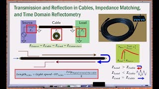
L-section matching networks are essential components in RF circuit design, designed to match impedances effectively between a source and a load. An L-section network utilizes one inductor and one capacitor arranged in an L-shape. This can be done in two configurations:
- Series L-section: where the inductor is in series with the transmission line and the capacitor is placed parallel to the load.
- Parallel L-section: where the inductor is in parallel with the transmission line and the capacitor is series with the load.
To determine the appropriate values of the inductor and capacitor, engineers analyze the source and load impedances. Correct component values ensure that maximum power transfer occurs, adhering to the Maximum Power Transfer Theorem.
Advantages of L-section Matching Networks
- Simplicity: These networks are straightforward to design and implement.
- Cost-Effectiveness: They provide a practical solution without complex components.
- Narrow Frequency Range: L-section networks perform well within defined bandwidths, making them suitable for narrowband RF circuits, such as antennas and filter applications.
Understanding and applying L-section matching networks is critical for enhancing the efficiency of RF systems by minimizing signal reflections and optimizing power transfer.
Youtube Videos
Audio Book
Dive deep into the subject with an immersive audiobook experience.
Overview of L-section Matching Networks
Chapter 1 of 6
🔒 Unlock Audio Chapter
Sign up and enroll to access the full audio experience
Chapter Content
An L-section matching network consists of one inductor and one capacitor arranged in an L-shape. It is a simple and effective way to match impedance between a source and load. The components can be configured either in series or parallel.
Detailed Explanation
An L-section matching network is a circuit made up of two components: an inductor and a capacitor. When these components are combined in the shape of an 'L', they help connect a source (like a signal generator) to a load (like an antenna) effectively. The arrangement of the inductor and capacitor can either be in series, where they are in line with each other, or in parallel, where they connect alongside each other.
Examples & Analogies
Think of the L-section matching network like a puzzle piece that fits between a power outlet (source) and a lamp (load). Just as you might use an adapter to connect different plug types, the L-section matching network helps ensure that the electrical 'fit' between the source and load is correct, allowing electricity to flow smoothly with minimal loss.
Series L-section Configuration
Chapter 2 of 6
🔒 Unlock Audio Chapter
Sign up and enroll to access the full audio experience
Chapter Content
Series L-section: The inductor is in series with the transmission line, and the capacitor is placed in parallel with the load.
Detailed Explanation
In a series L-section configuration, the inductor is placed in line with the main transmission line carrying the signal, while the capacitor is connected next to the load it is trying to reach. This setup is designed to adjust the impedance seen by the load so that maximum power can be transferred from the source to the load, reducing any signal loss or reflection.
Examples & Analogies
Imagine a water pipe system where the inductor acts like a valve that controls water flow and the capacitor is like an additional reservoir that helps smooth out fluctuations. By carefully adjusting the valve and reservoir size, you can ensure that the right amount of water, akin to electrical energy, flows to your garden (load) without it spilling back into the tank (source).
Parallel L-section Configuration
Chapter 3 of 6
🔒 Unlock Audio Chapter
Sign up and enroll to access the full audio experience
Chapter Content
Parallel L-section: The inductor is in parallel with the transmission line, and the capacitor is placed in series with the load.
Detailed Explanation
In this configuration, the inductor runs alongside the transmission line, while the capacitor is directly in line with the load. This setup serves to create an impedance transformation that helps accommodate the load's needs better, enabling effective power transfer from the source through the transmission line.
Examples & Analogies
Think of the parallel L-section like a dual-carriage road where each lane has a different purpose. One lane (the inductor) runs parallel to the main road (transmission line) while the exit ramp (capacitor) leads directly to a parking lot (load). This allows cars (electrical signals) to choose the best path to reach their destination without unnecessary delays or collisions.
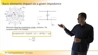
Impedance Transformation
Chapter 4 of 6
🔒 Unlock Audio Chapter
Sign up and enroll to access the full audio experience
Chapter Content
Impedance Transformation: The values of the inductor and capacitor are selected based on the source and load impedances to achieve maximum power transfer.
Detailed Explanation
For the L-section matching network to work effectively, the values of the inductor and capacitor must be carefully chosen based on the specific impedance values of both the source and the load. This selection ensures that the impedance at the input and output matches as closely as possible, therefore maximizing power transfer and reducing reflections that may occur due to impedance mismatch.
Examples & Analogies
Imagine tuning a guitar to ensure all strings are at the right pitch for the perfect harmony. In the same way, selecting the correct values for the inductor and capacitor is like tuning the matching network so that the signal fits perfectly from the source to the load, ensuring that all the energy is used efficiently without wasted reflections.
Advantages of L-section Matching Networks
Chapter 5 of 6
🔒 Unlock Audio Chapter
Sign up and enroll to access the full audio experience
Chapter Content
Advantages: Simple and cost-effective solution. Works well for narrow frequency bands.
Detailed Explanation
L-section matching networks are valued for their simplicity and cost-effectiveness. They are straightforward to design and implement, making them ideal for situations where high complexity is not needed. They specifically excel in narrow frequency ranges, allowing for effective impedance matching without requiring sophisticated components.
Examples & Analogies
Consider making a sandwich. You need just a few simple ingredients—not anything elaborate—to create something tasty quickly. Similarly, an L-section matching network uses just an inductor and a capacitor to achieve efficient impedance matching, much like how a simple sandwich can satisfy your hunger without the fuss of gourmet ingredients.
Applications of L-section Matching Networks
Chapter 6 of 6
🔒 Unlock Audio Chapter
Sign up and enroll to access the full audio experience
Chapter Content
Applications: Often used in narrowband RF circuits like antennas and filter networks.
Detailed Explanation
L-section matching networks are commonly used in narrowband RF (Radio Frequency) circuits, such as in antennas and filter networks. These applications require precise matching at specific frequencies to ensure that the signals are transmitted efficiently without unwanted interference or loss.
Examples & Analogies
Think of tuning a radio to catch a specific station's frequency. Just as you have to dial in the right setting to hear your favorite music clearly, L-section matching networks ensure that RF circuits are aligned perfectly for the specific frequencies they need to operate on, allowing for optimal performance and clarity without noise from other stations.
Key Concepts
-
L-section Matching Networks: Configurations of inductors and capacitors designed for impedance matching.
-
Impedance Transformation: The process of adjusting component values to achieve desired load conditions.
-
Narrow Frequency Band: The characteristic that defines the limited operational frequency range where L-section networks are effective.
Examples & Applications
An L-section matching network might be used in a RF transmitter to ensure that the output power is maximized when delivered to the antenna.
A simple L-section circuit could be implemented in a radio receiver to match the load impedance with the internal components, optimizing the signal clarity.
Memory Aids
Interactive tools to help you remember key concepts
Rhymes
L and C, in harmony, matching circuits, oh so free!
Stories
Imagine a conductor at a dance, pairing an inductor with a capacitor for the perfect match – that’s how they work together in L-networks.
Memory Tools
Remember 'L' and 'C' for 'Load' and 'Capacitance' when thinking about impedance matching!
Acronyms
Think of 'MATCH' – M for Maximum Power, A for Analyze components, T for Tune the network, C for Capacitance, H for Harmonics.
Flash Cards
Glossary
- Impedance Matching
The process of making the source and load impedances equal to maximize power transfer and minimize signal reflection.
- Lsection Matching Network
A configuration using one inductor and one capacitor in either series or parallel to match impedances.
- Inductor
A passive electrical component that stores energy in a magnetic field.
- Capacitor
A passive electrical component that stores energy in an electric field.
- Maximum Power Transfer Theorem
States that maximum power is transferred when the load impedance is equal to the complex conjugate of the source impedance.
Reference links
Supplementary resources to enhance your learning experience.