
Principles of Impedance Matching
Interactive Audio Lesson
Listen to a student-teacher conversation explaining the topic in a relatable way.
Introduction to Impedance Matching
🔒 Unlock Audio Lesson
Sign up and enroll to listen to this audio lesson

Today we will discuss the importance of impedance matching in RF and HF circuits. Can anyone tell me what impedance is?

Is it the opposition to current flow in an AC circuit?
Exactly! Impedance combines resistance, inductance, and capacitance. How do you think mismatched impedance affects circuit performance?

It could cause signal loss or distortion?
Correct! Signal reflection and distortion happen when the impedances do not match, which is critical to understand.

What does it mean to align impedance values across the circuit?
Good question! Aligning impedance values ensures maximum power transfer and minimized reflections—this is what impedance matching aims to achieve. Remember the acronym P2M: Power transfer, Minimal reflection.
Maximum Power Transfer Theorem
🔒 Unlock Audio Lesson
Sign up and enroll to listen to this audio lesson

Let's explore the Maximum Power Transfer Theorem. Can anyone state what it says?

It says that maximum power is transferred when the load impedance equals the source impedance?
That's right! For reactive impedances, remember that we match to the complex conjugate of the source impedance. Why do we think this is crucial in applications like antennas?
Because antennas need to efficiently send and receive signals?
Exactly! Ensuring that the source and load impedances match optimizes power output, which is vital for effective communication.
Can you explain what happens during an impedance mismatch?
Certainly! Impedance mismatches lead to reflections, which can interfere with signals. This is captured by the reflection coefficient. Remember Γ (Gamma) indicates how much power is reflected.
Impedance Matching Methods
🔒 Unlock Audio Lesson
Sign up and enroll to listen to this audio lesson
Now let’s talk about methods for impedance matching. What’s one method we can use?
Transformers?
Exactly! Transformers allow us to match impedances through their turns ratio. Can anyone explain how it works?
The impedance ratio is related to the square of the turns ratio?
Right! There are also L-section and Pi-section matching networks. What is an advantage of using L-section matching?
It's simple and cost-effective?
Exactly! On the other hand, Pi-section networks offer broader frequency mismatch tolerability. It’s about finding the right method for your specific application.
Applications of Impedance Matching
🔒 Unlock Audio Lesson
Sign up and enroll to listen to this audio lesson
Finally, let's discuss where impedance matching is applied in real-world scenarios. What are some applications you can think of?
In antennas and communication systems?
Correct! Impedance matching is crucial in these systems. What would happen without proper matching?
We'd lose signal strength and have distortion?
Exactly! Additionally, practical considerations like frequency range and efficiency also play significant roles. Always consider matching at different points: source, load, and line.
Is it always necessary to match at each point?
Not always, but for optimal performance, especially in complex systems, it’s generally recommended to minimize reflections and maximize efficiency.
Introduction & Overview
Read summaries of the section's main ideas at different levels of detail.
Quick Overview
Standard
This section introduces the principles of impedance matching, emphasizing the significance of matching impedances in RF circuits to prevent signal loss and reflections. Key methods, such as transformers and matching networks, are highlighted, alongside important concepts like the Maximum Power Transfer Theorem.
Detailed
Principles of Impedance Matching
Introduction to Impedance Matching
Impedance matching is a crucial concept in RF (Radio Frequency) and HF (High Frequency) circuits that ensures efficient power transfer and minimizes signal reflection. Impedance is defined as the opposition to current flow in an AC circuit and encompasses resistance, inductance, and capacitance. When there is an impedance mismatch between components in RF circuits, it leads to signal loss, distortion, and unwanted reflections.
Key Principles of Impedance Matching
Maximum Power Transfer Theorem
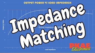
This theorem asserts that maximum power is transferred when the load impedance equals the complex conjugate of the source impedance. This principle is fundamental in various power transfer applications, like antennas and receivers.
Impedance Mismatch Consequences
Impedance mismatches can cause:
- Reflection Coefficient: Indicates how much signal is reflected; a coefficient of Γ=0 indicates perfect matching.
- Standing Wave Ratio (SWR): Measures the impedance mismatch severity.
- Signal Loss and Efficiency: Reduces circuit efficiency by reflecting power rather than transferring it.
Impedance Matching Methods
Using Transformers
Transformers match impedances through their turns ratio, determining impedance transformation. Key advantages include high efficiency and no transformations losses.
L-section Matching Networks
L-section networks use one inductor and one capacitor for simple impedance matching in narrow bands. They are cost-effective and easy to implement.
Pi-section Matching Networks
These networks offer greater flexibility and better matching over wider frequency ranges, suitable for applications like wideband amplifiers.
Stub Matching
This technique uses short transmission lines, or stubs, to match impedances, featuring both open-circuited and short-circuited configurations.
Practical Considerations
Design must consider frequency range and matching points across different components to ensure efficient power transfer and minimal reflection.
Summary of Key Concepts
Impedance matching is vital in RF and HF circuits for maximizing power transfer. Passive components play a significant role, and techniques like transformers, L-section, and pi-section networks are crucial for effective matching.
Youtube Videos
Audio Book
Dive deep into the subject with an immersive audiobook experience.
Introduction to Impedance Matching
Chapter 1 of 4
🔒 Unlock Audio Chapter
Sign up and enroll to access the full audio experience
Chapter Content
Impedance matching is a crucial concept in RF (Radio Frequency) and HF (High Frequency) circuits to ensure efficient power transfer and to minimize signal reflection. Impedance is the opposition to the flow of current in an alternating current (AC) circuit, which includes resistance, inductance, and capacitance.
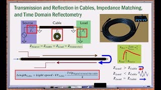
In RF circuits, impedance mismatches can cause signal loss, distortion, and reflection at the interface between different components. These reflections occur when the impedance of the source, transmission line, and load are not equal, leading to inefficient energy transfer and interference. Impedance matching aims to align the impedance values across all stages of a circuit to maximize the power transfer and minimize reflections.
Detailed Explanation
Impedance matching is essential in electrical engineering, especially in circuits that operate at high frequencies like RF and HF. It makes sure that the devices connected in a circuit work efficiently together. Impedance itself is how much a circuit resists current flowing through it, influenced by factors like resistance (how much a device opposes current flow) and reactance (which comes from inductors and capacitors). When devices have different impedance levels, it results in energy loss, distorted signals, or reflections, where some of the energy bounces back instead of passing through. The goal of impedance matching is to make sure that all parts of the circuit have the same impedance, thereby allowing maximum energy to flow and minimizing disturbances.
Examples & Analogies
Think of impedance matching like trying to pour water from one container to another. If you use a funnel (the right equipment), all the water flows perfectly into the next container. But if the funnel is too small (different impedance), the water might spill or even bounce back, just like how an electrical signal reflects back when there's a mismatch. Proper matching ensures nothing is wasted, similar to ensuring all water successfully moves to where it needs to go.
Maximum Power Transfer Theorem
Chapter 2 of 4
🔒 Unlock Audio Chapter
Sign up and enroll to access the full audio experience
Chapter Content
The Maximum Power Transfer Theorem states that maximum power is transferred from a source to a load when the impedance of the load is equal to the complex conjugate of the source impedance.
For real-valued resistive impedance, the source and load impedance should be equal:
Zsource = Zload
For reactive impedance (complex impedance), the conjugate matching condition applies:
Zsource = Zload∗
Where:
● Zsource is the impedance of the source.
● Zload is the impedance of the load.
● Zload∗ is the complex conjugate of the load impedance.
This principle is particularly important in power transfer applications such as antennas, transmitters, and receivers.
Detailed Explanation
The Maximum Power Transfer Theorem is a fundamental concept that tells us how to transfer power most efficiently in electrical circuits. It posits that to achieve optimal power delivery, the load impedance must match the source's impedance. For instance, if two resistors are connected in a circuit and their resistances are equal, more energy flows to the load than if they are mismatched. This is applicable in complex circuits as well, where reactive elements (like inductors and capacitors) also factor into impedance. Understanding this theorem helps engineers design systems like antennae by ensuring they are matched correctly for maximum efficiency.
Examples & Analogies
Imagine you are at a concert, and the sound from the speakers (the source) is perfectly matched to the audience (the load). If the speakers are too loud or too quiet (mismatched impedance), the sound won't be clear or won’t reach everyone equally. Just like how the right volume ensures the best sound, matching the right impedance allows the best power transfer in circuits.
Impedance Mismatch Consequences
Chapter 3 of 4
🔒 Unlock Audio Chapter
Sign up and enroll to access the full audio experience
Chapter Content
● Reflection Coefficient: If there is an impedance mismatch, part of the signal is reflected back to the source, which can interfere with the signal and cause standing waves on transmission lines. The reflection coefficient Γ is given by:
Γ = (Zload − Zsource) / (Zload + Zsource)
A reflection coefficient of Γ = 0 indicates perfect impedance matching with no signal reflection.
● Standing Wave Ratio (SWR): The Standing Wave Ratio (SWR) is a measure of the severity of impedance mismatching, defined as the ratio of the maximum to minimum voltages along the transmission line. An ideal SWR is 1:1, indicating perfect impedance matching.
● Signal Loss and Efficiency: Mismatched impedance reduces the efficiency of the circuit, as power is lost due to reflection rather than being transferred to the load.
Detailed Explanation
When there's an impedance mismatch in a circuit, several negative effects occur. The reflection coefficient quantifies how much of the signal bounces back to the source, which can cause interference and create standing waves along the transmission lines, disrupting the overall signal quality. The Standing Wave Ratio (SWR) helps visualize this issue; an ideal SWR ratio is 1:1, meaning there is no reflected power, while any discrepancy indicates mismatching. Consequently, overall efficiency drops because energy intended for the load is reflected back instead of being used, leading to wasted power and distortion in signals.
Examples & Analogies
Returning to the concert analogy, if some of the sound waves reflect back instead of reaching the audience, then the overall experience diminishes. This reflection of sound is akin to signals reflecting in an impedance mismatch. If the microphone’s output (source) doesn’t align with the sound system (load), parts of the sound may go unheard or create echoes, which can confuse or overwhelm listeners just as mismatched impedance can distort electronic signals.
Impedance Matching Methods
Chapter 4 of 4
🔒 Unlock Audio Chapter
Sign up and enroll to access the full audio experience
Chapter Content
● Using Transformers: Transformers are commonly used in RF and HF circuits to match impedances between components with different impedance values. The transformer’s turns ratio determines the impedance transformation.
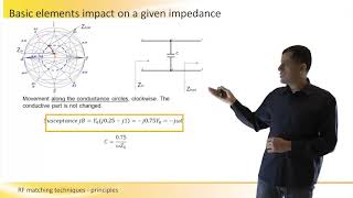
● L-section Matching Networks: An L-section matching network consists of one inductor and one capacitor arranged in an L-shape. It is a simple and effective way to match impedance between a source and load. The components can be configured either in series or parallel.
● Pi-section Matching Networks: A pi-section network is similar to the L-section, but it involves two inductors and one capacitor or two capacitors and one inductor, forming a "pi" shape. This type of matching network is more flexible and is used when a broader frequency range is needed.
● Stub Matching: Stub matching is a technique used to match the impedance of a transmission line to a load using a short piece of transmission line, called a stub, which is connected in parallel or series with the main transmission line.
Detailed Explanation
There are several methods to achieve impedance matching, each tailored to specific applications and needs. Transformers change the impedance based on their turn ratio—higher ratios result in stepped-up impedance and vice versa. The L-section network is a simple design that utilizes an inductor and capacitor to achieve matching; they can be configured differently depending on circuit requirements. The more flexible Pi-section network serves a similar purpose but can cover broader frequency ranges due to the additional components. Lastly, stub matching uses short lengths of transmission lines to adjust the impedance effectively, often used in simpler RF configurations where precision is necessary.
Examples & Analogies
Consider how different connectors can adapt your phone's charger to fit various sockets. Transformers act like these connectors, stepping up or down charge levels. The L-section or Pi-section networks can be compared to different types of adapter plugs you use depending on which country you're in—both work to make your device compatible, just like these networks work to match electrical components effectively. Stub matching can be seen as using a specific type of wire to ensure smooth connections at the right lengths, just like ensuring you always have the correct extension cord to reach an outlet.
Key Concepts
-
Impedance Matching: Essential for efficient power transfer in RF circuits to minimize signal reflection.
-
Maximum Power Transfer Theorem: States that load impedance should equal the source impedance for maximum power transfer.
-
Impedance Mismatch: Causes signal reflections, distortion, and reduced circuit efficiency.
-
Transformers: Used to match impedances efficiently with their turns ratio.
-
Electrical Matching Networks: Configurations like L-section, Pi-section, and stub matching to achieve impedance matching.
Examples & Applications
In radio transmissions, using transformers to match the impedance between an antenna and transmitter improves signal clarity.
An L-section network is applied in a narrow-band RF filter circuit to match the load to the source impedance efficiently.
Memory Aids
Interactive tools to help you remember key concepts
Rhymes
To match impedance, don’t just guess, align them right for power success!
Stories
Imagine a dance where two partners must be in sync to perform perfectly. If one steps out of line, the performance falters—much like how mismatched impedance disrupts signal transmission.
Memory Tools
Remember 'M-P-P-T' for Matching: Maximum Power Transfer Theorem.
Acronyms
Use the acronym MISMATCH
Maximum Impedance Stability Means Avoiding Transmission Choppiness.
Flash Cards
Glossary
- Impedance
The opposition to the flow of current in an AC circuit, encompassing resistance, inductance, and capacitance.
- Reflection Coefficient (Γ)
A measure of how much signal is reflected due to impedance mismatch, calculated as (Zload - Zsource) / (Zload + Zsource).
- Standing Wave Ratio (SWR)
A measure of the severity of impedance mismatching, defined as the ratio of maximum to minimum voltages along a transmission line.
- Maximum Power Transfer Theorem
States that maximum power is transferred when load impedance equals the source impedance, or its complex conjugate for reactive loads.
- Lsection Matching Network
A simple circuit configuration using one inductor and one capacitor for impedance matching.
- Pisection Matching Network
An impedance matching network composed of two inductors and one capacitor (or vice versa), offering better matching over a broader frequency range.
- Stub Matching
A technique that employs short lengths of transmission lines (stubs) to achieve impedance matching.
Reference links
Supplementary resources to enhance your learning experience.