
Impedance Mismatch Consequences
Interactive Audio Lesson
Listen to a student-teacher conversation explaining the topic in a relatable way.
Reflection Coefficient
🔒 Unlock Audio Lesson
Sign up and enroll to listen to this audio lesson

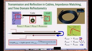
Let's start with the reflection coefficient, denoted by Γ. This parameter measures the portion of the signal that is reflected back to the source in the event of an impedance mismatch. Could someone express in their own words what they understand about the reflection coefficient?

It seems like if the impedances aren't matched, some signal just bounces back and doesn't go where it should.

So, if Γ equals zero, that means everything is perfectly matched, right?
Exactly! That would mean no signal reflection occurs, resulting in efficient energy transfer. Anyone know the formula for calculating this?

I think it’s Γ = (Z_load - Z_source) / (Z_load + Z_source).
Correct! Remember that a higher reflection coefficient signifies more significant mismatches, which can disrupt circuit performance. It’s crucial for tuning circuits and RF applications.
To summarize, the reflection coefficient quantifies how much of a signal is reflected back. Lower values indicate better matching. Let's keep this idea moving as we talk about the standing wave ratio.
Standing Wave Ratio (SWR)
🔒 Unlock Audio Lesson
Sign up and enroll to listen to this audio lesson

Now, let’s delve into the Standing Wave Ratio or SWR. Who can explain what SWR signifies in the context of impedance mismatching?

I believe it's the ratio of maximum to minimum voltage on a transmission line?
Correct! An ideal SWR of 1:1 indicates perfect impedance matching. What happens if the SWR ratio increases?
A higher ratio means larger differences in voltage levels, leading to inefficient power transfer?
Absolutely! Increased SWR can cause not only power loss but also signal distortion. Any ideas on how we could minimize SWR in practical scenarios?
By using impedance matching networks, right?
Exactly! To summarize, SWR is crucial for assessing circuit efficiency. Lower ratios are desired for optimal performance.
Signal Loss and Efficiency
🔒 Unlock Audio Lesson
Sign up and enroll to listen to this audio lesson
Finally, let's talk about signal loss and efficiency. Can someone explain how impedance mismatches can affect the overall efficiency of a circuit?
When impedance is mismatched, part of the signal is lost due to reflections, so less power reaches the load!
Exactly correct! So, when engineers design circuits, what do they prioritize to ensure efficiency?
They need to match the impedances across the circuit stages, right?
Yes! Proper impedance matching ensures maximum power transfer and minimizes signal reflection, maintaining circuit efficiency. Well done everyone!
Introduction & Overview
Read summaries of the section's main ideas at different levels of detail.
Quick Overview
Standard
Impedance mismatches can significantly affect circuit performance, leading to reflection of signals, creation of standing waves, and loss of efficiency. Key concepts include the reflection coefficient, standing wave ratio (SWR), and the impact of these mismatches on signal power transfer.
Detailed
Detailed Summary
In RF and HF circuits, impedance mismatches can lead to various detrimental consequences affecting performance. The Reflection Coefficient (Γ) quantifies how much of an incident signal is reflected back towards the source due to impedance mismatch. It is defined as:
$$Γ = \frac{Z_{load} - Z_{source}}{Z_{load} + Z_{source}}$$
A reflection coefficient of 0 indicates perfect matching, with no reflected signal. Conversely, a high reflection coefficient results in power losses and interference.
Another critical metric is the Standing Wave Ratio (SWR), which measures voltage variations along a transmission line caused by reflections. An ideal SWR of 1:1 signifies perfect impedance matching, whereas higher ratios indicate worse mismatches, leading to further efficiency losses, as reflected power does not reach the load.
Overall, impedance mismatches can significantly hinder circuit performance and efficiency, indicating the importance of effective impedance matching strategies to maximize power transfer and minimize reflections.
Youtube Videos
Audio Book
Dive deep into the subject with an immersive audiobook experience.
Reflection Coefficient
Chapter 1 of 3
🔒 Unlock Audio Chapter
Sign up and enroll to access the full audio experience
Chapter Content
If there is an impedance mismatch, part of the signal is reflected back to the source, which can interfere with the signal and cause standing waves on transmission lines. The reflection coefficient Γ is given by:
Γ = \frac{Z_{load} - Z_{source}}{Z_{load} + Z_{source}}
A reflection coefficient of Γ = 0 indicates perfect impedance matching with no signal reflection.
Detailed Explanation
The reflection coefficient (Γ) is a measure of how much of an incoming signal is reflected back due to impedance mismatch. When two components with different impedances are connected, the mismatch can cause some of the electrical energy to bounce back toward the source instead of passing through. This can lead to disturbances in the signal, like standing waves, which are harmful in communication systems. A reflection coefficient of zero (Γ = 0) means that all the signal is transmitted without reflection, ensuring optimal performance.
Examples & Analogies
Think of a reflection coefficient like sound echoing in a tunnel. If the tunnel is perfectly designed with the right shape (like perfect impedance matching), your voice travels through without bouncing back. But if there are barriers that aren't aligned (impedance mismatch), some of your voice will bounce back and interfere with what you're saying.
Standing Wave Ratio (SWR)
Chapter 2 of 3
🔒 Unlock Audio Chapter
Sign up and enroll to access the full audio experience
Chapter Content
The Standing Wave Ratio (SWR) is a measure of the severity of impedance mismatching, defined as the ratio of the maximum to minimum voltages along the transmission line. An ideal SWR is 1:1, indicating perfect impedance matching.
Detailed Explanation
Standing Wave Ratio (SWR) quantifies the effectiveness of impedance matching in a system. It compares the highest voltage to the lowest voltage along the transmission line. A SWR of 1:1 suggests that the line is perfectly matched, meaning there are no voltage variations due to reflections. As the SWR increases, it indicates worse mismatching, which can lead to energy losses and potential signal distortion.
Examples & Analogies
Imagine a group of people singing in harmony. If every person is perfectly in tune (like having a SWR of 1:1), the sound is smooth and coherent. But if some people sing off-key (high SWR), it creates a chaotic sound, drawing attention away from the main performance, similar to how an impedance mismatch detracts from signal quality.
Signal Loss and Efficiency
Chapter 3 of 3
🔒 Unlock Audio Chapter
Sign up and enroll to access the full audio experience
Chapter Content
Mismatched impedance reduces the efficiency of the circuit, as power is lost due to reflection rather than being transferred to the load.
Detailed Explanation
When the impedance in a circuit is not matched, a portion of the power intended for the load gets lost because it reflects back instead of being utilized effectively. This leads to decreased overall efficiency, meaning that the system cannot perform at its optimal level. Ensuring that impedance matches allows for better power usage and signal integrity in circuits, especially in communication and audio systems.
Examples & Analogies
Think of a garden hose connected to a spray nozzle. If the nozzle is too big (mismatched impedance), much of the water pressure is lost, making it ineffective for watering plants. However, if the nozzle fits well with the hose (matched impedance), every bit of water flows out efficiently, ensuring the garden gets the right amount of water.
Key Concepts
-
Reflection Coefficient: Indicates how much signal is reflected back due to impedance mismatch.
-
Standing Wave Ratio (SWR): The ratio of voltage peaks and troughs on a transmission line, reflecting mismatch severity.
-
Efficiency: The effectiveness of power transfer relative to the power lost due to reflection.
Examples & Applications
In a transmission line connected to a load with significantly different impedance, a considerable portion of the signal may be reflected back, causing inefficiency.
A radio antenna designed with poor impedance matching may experience a high SWR, resulting in significant power loss and reduced signal quality.
Memory Aids
Interactive tools to help you remember key concepts
Rhymes
Reflection ripples, SWR in sight, Match your impedances to keep it right.
Stories
Imagine a water pipe where water flows smoothly. If a pipe section gets narrowed, some water pushes back. This is like signals in a circuit; mismatches cause reflections just like water backing up.
Memory Tools
Remember 'Reflected, Standing, Efficiency' (RSE) to capture the key points of impedance mismatch consequences.
Acronyms
Use 'RES' for Reflection, Efficiency, SWR to recall key metrics.
Flash Cards
Glossary
- Reflection Coefficient
A measure of the amount of signal reflected back to the source due to impedance mismatch.
- Standing Wave Ratio (SWR)
A measure of the voltage variations along a transmission line, indicating the severity of impedance mismatching.
- Impedance Mismatch
Occurs when the impedances of different components in a circuit are not equal, leading to ineffective power transfer.
- Efficiency
The ratio of power transferred to the load versus the power reflected back due to mismatches.
Reference links
Supplementary resources to enhance your learning experience.