
Cascaded Amplifier Design
Interactive Audio Lesson
Listen to a student-teacher conversation explaining the topic in a relatable way.
Introducing Cascaded Amplifiers
🔒 Unlock Audio Lesson
Sign up and enroll to listen to this audio lesson

Today we'll be diving into cascaded amplifier designs, which are crucial for enhancing signal strength in electronic circuits. Can anyone tell me what a cascaded amplifier setup generally looks like?

Isn't it where you connect multiple amplifier stages together?
Exactly! Connecting stages allows us to increase overall gain. Does anyone know how we calculate the total gain of a cascaded amplifier?

Is it something like adding the gains?
Close! We actually multiply the gains of each stage. So if Stage 1 has a gain of `A_{V1}` and Stage 2 has `A_{V2}`, the total gain is \( A_{V(total)} = A_{V1} \times A_{V2} \).
Components of Cascaded Circuits
🔒 Unlock Audio Lesson
Sign up and enroll to listen to this audio lesson

Now that we understand the gain calculation, what components do we typically use in a cascaded amplifier?

Do we use transistors and capacitors?
Exactly! A common configuration is the connection of a Common Emitter (CE) stage followed by a Common Collector (CC) stage, linked by coupling capacitors to block DC but allow AC signals to pass. Why do you think this configuration is useful?

It helps to amplify the signal while maintaining good input and output impedance.
Correct! By using the CC stage after a CE stage, we can effectively buffer the output.
Practical Applications of Cascaded Amplifiers
🔒 Unlock Audio Lesson
Sign up and enroll to listen to this audio lesson
Can anyone think of some applications where cascaded amplifiers might be used?
What about in audio amplification systems?
Absolutely! Audio systems often use cascaded amplifiers to boost low-level audio signals to levels suitable for driving speakers. Can anyone think of other scenarios?
How about in communication devices?
Exactly, they're used in radios and televisions to amplify weak signals to improve clarity and strength!
Introduction & Overview
Read summaries of the section's main ideas at different levels of detail.
Quick Overview
Standard
This section focuses on the design principles of cascaded amplifiers, emphasizing the multiplication of individual stage gains to achieve desired overall amplification. Understanding how to correctly interconnect these stages is crucial for effective signal amplification in various applications.
Detailed
Cascaded Amplifier Design
Cascaded amplifiers involve connecting multiple amplifier stages together to achieve improved total gain. In this design class, we specifically utilize the formula for calculating total gain, expressed as:
\[ A_{V(total)} = A_{V1} \times A_{V2} \]
This equation highlights that the overall gain of the cascaded system is the product of the individual gains of each stage. In this context, a typical configuration might include a Common Emitter (CE) stage and a Common Collector (CC) stage linked through a coupling capacitor. This setup helps in amplifying low-level signals effectively.
Cascaded designs are significant in various applications, notably in communications and signal processing, where high gain and stability are critical. Understanding the principles of cascading is essential for engineers tasked with creating efficient electronic systems.
Youtube Videos


Audio Book
Dive deep into the subject with an immersive audiobook experience.
Cascaded Amplifier Stages
Chapter 1 of 2
🔒 Unlock Audio Chapter
Sign up and enroll to access the full audio experience
Chapter Content
Stage 1 (CE) Stage 2 (CC)
Z1 Z2
V1─□□□─┬─────────□□□─V2
│ ▲
└─Coupling Cap
Detailed Explanation
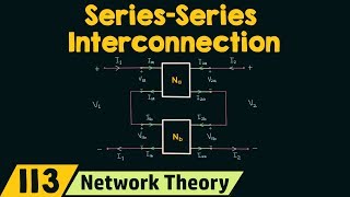
In this section, we discuss the design of cascaded amplifiers, which consist of multiple amplification stages. Here, we have two stages: Stage 1 is a Common Emitter (CE) amplifier, and Stage 2 is a Common Collector (CC) amplifier. 'Z1' and 'Z2' represent the input and output impedances of the respective stages. The voltage gain from Stage 1 (A_V1) is connected to Stage 2. A coupling capacitor is used to connect these two stages while blocking any DC component, allowing only the AC signals to pass through.
Examples & Analogies
Think of a cascaded amplifier like a relay race. Each runner (amplifier stage) has to pass the baton (signal) to the next runner without dropping it. The coupling capacitor acts like a handoff technique ensuring the baton (AC signal) passes smoothly without interference from other factors (like DC components). Just as the speed of the relay team depends on how quickly the handoff occurs, the overall gain of the amplifier depends on how effectively each stage amplifies the signal.
Total Gain Calculation
Chapter 2 of 2
🔒 Unlock Audio Chapter
Sign up and enroll to access the full audio experience
Chapter Content
- Total Gain:
\[
A_{V(total)} = A_{V1} × A_{V2}
\]
Detailed Explanation
The total gain of the cascaded amplifier is determined by multiplying the gains of each individual stage. If A_V1 is the voltage gain of the first stage and A_V2 is the voltage gain of the second stage, the overall gain (A_V(total)) can be calculated using this formula. This multiplication means that the performance of the entire cascaded system is merely the product of the performances of the individual stages.
Examples & Analogies
Imagine multiplying the efficiency of two different engines in a car. If the first engine can transform fuel into 10% increased speed and the second engine can do so with 20%, the overall speed boost isn't just a simple addition but a product of both efficiencies—resulting in a much higher combined speed on the road, similar to how two amplifier stages work together.
Key Concepts
-
Cascaded Amplifier: Connecting multiple amplifiers to achieve a desired gain.
-
Common Emitter (CE): A high-gain transistor amplifier configuration.
-
Common Collector (CC): A buffer configuration with low output impedance.
-
Coupling Capacitors: Components to connect amplifier stages while blocking DC.
Examples & Applications
A practical example of a two-stage amplifier that uses a CE and a CC configuration to amplify an audio signal.
In a communication circuit, a cascaded amplifier setup is used to enhance signal levels before processing.
Memory Aids
Interactive tools to help you remember key concepts
Rhymes
In stages we cascade, amplifying sound, with gain combined, quality unbound.
Stories
Imagine a band where each musician plays beautifully, their melodies blending into a rich symphony, much like cascaded amplifiers combining their gains for a powerful output.
Memory Tools
CECC: Common Emitter and Common Collector - for Amplifiers like a 'Clever Electrical Cascade.'
Acronyms
CAG
'Cascaded Amplifier Gain' — Remember this when calculating the total gain.
Flash Cards
Glossary
- Cascaded Amplifier
A configuration of multiple amplifiers connected in sequence, where the output of one stage feeds the input of the next.
- Common Emitter (CE)
A transistor amplifier configuration that provides high gain and is commonly used in cascaded designs.
- Common Collector (CC)
A buffer configuration that provides low output impedance, often used to interface between two stages of amplifiers.
- Coupling Capacitor
A capacitor used to connect two amplifier stages while blocking DC components.
- Total Gain
The combined amplification factor of multiple cascaded amplifier stages, calculated as the product of individual stage gains.
Reference links
Supplementary resources to enhance your learning experience.