
Simulation Techniques
Interactive Audio Lesson
Listen to a student-teacher conversation explaining the topic in a relatable way.
Introduction to Simulation Techniques
🔒 Unlock Audio Lesson
Sign up and enroll to listen to this audio lesson

Today, we will explore simulation techniques, specifically how they apply to evaluating two-port networks. Can anyone tell me why simulations are valuable in engineering?

I think they help predict the behavior of circuits without building them.
Exactly! Simulation allows us to test and validate our designs in a virtual environment. What tools have you heard of that aid in simulations?

SPICE is a common one used for circuit simulations.
Correct, SPICE stands for Simulation Program with Integrated Circuit Emphasis. Let's cover how we can set up a basic simulation for cascading amplifiers.
Setting Up a SPICE Simulation
🔒 Unlock Audio Lesson
Sign up and enroll to listen to this audio lesson

We'll look at the SPICE code used for our cascaded amplifier example. Can anyone identify how subcircuits are used?

Are subcircuits like building blocks for the main circuit?
"Yes! Subcircuits encapsulate detailed circuit designs into manageable sections. Here's a snippet:
Interpreting Simulation Results
🔒 Unlock Audio Lesson
Sign up and enroll to listen to this audio lesson
After running our simulation, we should look for specific outputs. What would you like to observe from our cascaded amplifier?
I’d want to see the voltage gain.
"Great! In our SPICE code, we would utilize the `.probe` command to check voltage levels. For example:
Best Practices in Simulation
🔒 Unlock Audio Lesson
Sign up and enroll to listen to this audio lesson
To close our section, let's discuss some best practices when running SPICE simulations. Who can start with one recommendation?
Always double-check your component values and connections; even small errors can lead to big discrepancies.
That's an excellent point! It's also crucial to choose appropriate simulation parameters, such as frequency range. Does anyone have other points to add?

Using a variety of test scenarios can help ensure reliability.
Absolutely, simulating under different conditions can reveal weaknesses in your design. Let's recap what we've learned today.
Introduction & Overview
Read summaries of the section's main ideas at different levels of detail.
Quick Overview
Standard
The section covers the importance of simulation techniques to validate the performance of cascaded amplifiers and other networks using SPICE commands. It includes examples of syntax for setting up simulations and the expected outputs, emphasizing their role in ensuring that theoretical designs align with practical performance.
Detailed
Simulation Techniques
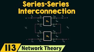
In this section, we delve into the use of simulation techniques as an integral method for verification in two-port network interconnections. Simulations allow engineers and designers to validate the functionality and performance of complex networks without the need for physical prototypes. Utilizing a tool like SPICE (Simulation Program with Integrated Circuit Emphasis) can significantly reduce development time and enhance accuracy in performance predictions.
The section introduces a typical SPICE setup for cascading amplifiers, where two amplifier stages are modeled using subcircuits in SPICE code. A brief template is provided:
This snippet illustrates how to configure the simulation for a frequency sweep across different parameters, allowing the user to probe specific voltages at designated points in the circuit. By comparing the simulated outputs with theoretical values, students and professionals can confirm the accuracy of their designs and adjust components as necessary. This enhances understanding of circuit behavior and is a critical skill in modern electronics design.
Youtube Videos


Audio Book
Dive deep into the subject with an immersive audiobook experience.
Cascaded Amplifier Example Setup
Chapter 1 of 4
🔒 Unlock Audio Chapter
Sign up and enroll to access the full audio experience
Chapter Content
* Cascaded Amplifier Example
X1 1 2 CE_Amplifier
X2 2 3 CC_Buffer
.subckt CE_Amplifier ...
.subckt CC_Buffer ...
.ac dec 10 1Hz 100MHz
.probe V(3)/V(1)
.end
Detailed Explanation
This chunk introduces a specific example of how to simulate a cascaded amplifier setup using a circuit simulation tool like SPICE. In this code snippet, we define two components: 'CE_Amplifier' and 'CC_Buffer'. The 'X1' and 'X2' denote the connections between these components, with 'X1' connecting the input to the first amplifier and 'X2' connecting the output of the first amplifier to the second. The '.ac' directive indicates that we want to perform an AC analysis from 1Hz to 100MHz, providing a broad frequency range to analyze the amplifier's performance over. The '.probe' command is used to measure the voltage at node '3' relative to node '1', which helps us examine the amplifier's gain.
Examples & Analogies
Think of the cascaded amplifiers like a relay race. Each runner (amplifier) has to pass the baton (signal) to the next runner smoothly. The SPICE simulation is like a coach analyzing how each runner performs at various speeds (frequencies), ensuring the transition of the baton is seamless throughout the race to maintain speed.
Subcircuits Definition
Chapter 2 of 4
🔒 Unlock Audio Chapter
Sign up and enroll to access the full audio experience
Chapter Content
.subckt CE_Amplifier ...
.subckt CC_Buffer ...
Detailed Explanation
This part defines subcircuits for the two different amplifying stages. Subcircuits are reusable building blocks in circuit simulations that encapsulate the details of a specific circuit configuration, allowing users to simplify their overall schematic while keeping complex details organized. Each subckt declaration shows that we will be defining the approach to how our CE amplifier and CC buffer work, which can be invoked anywhere in the main circuit without having to rewrite the entire circuit again.
Examples & Analogies
Consider subcircuits as recipes for your favorite dishes. You write down the ingredients and steps needed to prepare a dish once (subckt). Then, whenever you want to cook that dish, you simply refer to your recipe without needing to remember every little detail again.
AC Analysis Setup
Chapter 3 of 4
🔒 Unlock Audio Chapter
Sign up and enroll to access the full audio experience
Chapter Content
.ac dec 10 1Hz 100MHz
Detailed Explanation
The '.ac' command sets up an AC analysis, which is essential to determine how the circuit reacts to varying frequencies of input signals. The 'dec 10' portion specifies that the analysis should be done on a logarithmic scale with a decade frequency sweep, meaning that we will take measurements at frequencies that increase by a factor of ten (for example, 1Hz, 10Hz, 100Hz, etc.). The range from 1Hz to 100MHz means that the simulation will help us understand the circuit's performance across a very wide spectrum, critical for applications in communications and audio.
Examples & Analogies
Imagine you are testing a stereo system. An AC analysis is like playing music on the stereo and listening at different volume levels (frequencies). By testing from soft sounds (1Hz) to very loud sounds (100MHz), you determine at what level the stereo performs optimally or starts to distort.
Probing Voltage Measurements
Chapter 4 of 4
🔒 Unlock Audio Chapter
Sign up and enroll to access the full audio experience
Chapter Content
.probe V(3)/V(1)
Detailed Explanation
The '.probe' statement is used to collect data for analysis, specifically measuring the voltage at point '3' relative to point '1'. This allows the user to capture the circumstances under which the output voltage behaves in relation to the input voltage. This is crucial for assessing the gain of the amplifiers and overall circuit performance. In simulations, probing helps identify if the design meets the necessary specifications or requires adjustments.
Examples & Analogies
Think of this voltage probing as a detective taking measurements at a crime scene. Measuring voltage at various points in a circuit helps identify where things might be going wrong, akin to locating clues that lead to understanding the unfolding events in a case.
Key Concepts
-
Simulation Techniques: Methods used to accurately predict circuit behavior through modeling.
-
SPICE: A popular simulation tool that allows users to design and test circuits virtually.
-
Subcircuit: Modular sections of SPICE code that simplify complex circuit designs.
Examples & Applications
Setting up a basic cascaded amplifier using SPICE for frequency analysis.
Using the .probe command to evaluate output voltages in the simulation.
Memory Aids
Interactive tools to help you remember key concepts
Rhymes
SPICE is wise, it tests with ease; circuits it can tease, to make sure they please.
Stories
Imagine creating a robot using parts like resistors and transistors. You prototype it virtually in SPICE, checking each circuit layer before making it real!
Memory Tools
SPICE—Simulation Predicts Integrated Circuit Efficiency.
Acronyms
Use subcircuits to Simplify and Structure Your Designs.
Flash Cards
Glossary
- SPICE
A simulation program used to analyze and model electronic circuits.
- subcircuit
A defined segment within SPICE that represents a portion of a circuit allowing for modular design.
- probe
A SPICE command used to measure and output values at specified points in a circuit during simulation.
Reference links
Supplementary resources to enhance your learning experience.