
Analysis of the Common Collector Amplifier
Enroll to start learning
You’ve not yet enrolled in this course. Please enroll for free to listen to audio lessons, classroom podcasts and take practice test.
Interactive Audio Lesson
Listen to a student-teacher conversation explaining the topic in a relatable way.
Introduction to Common Collector Amplifier
🔒 Unlock Audio Lesson
Sign up and enroll to listen to this audio lesson

Welcome everyone! Today we will cover the common collector amplifier. Who can tell me what the primary function of an amplifier is?

Isn't it to increase the strength of a signal?
Exactly! We use amplifiers to boost the signal strength. The common collector amplifier is also called an emitter follower. It's known for having a high input resistance and a low output resistance. Can someone explain why these characteristics are beneficial?

High input resistance means it won’t load down the previous stage, right?
Correct! And low output resistance allows it to drive loads effectively. Remember the acronym HILR: High Input, Low Resistance. Let’s move forward!
Voltage Gain Calculation
🔒 Unlock Audio Lesson
Sign up and enroll to listen to this audio lesson

Now, let’s discuss the voltage gain. Can anyone tell me how we determine the voltage gain in a common collector amplifier?

I think it’s the ratio of the output voltage to the input voltage, but how do we derive that?
Great question! The output voltage is approximately equal to the input voltage, leading us to conclude that the voltage gain is close to 1. Does anybody remember how we arrived at that conclusion?

We considered the resistances involved and how they relate to the signal at the collector?
Exactly! When we express output voltage in terms of input voltage and resistances, the gain approaches 1 under certain conditions. Good work, everyone!
Resistance Analysis
🔒 Unlock Audio Lesson
Sign up and enroll to listen to this audio lesson
Let’s shift our focus to resistance. Can we discuss what happens to input resistance when we connect a resistance at the collector?
I believe it increases the input resistance, making it more favorable for use?
Exactly right! This increase occurs because the resistance at the collector adds to the overall input resistance. Let's remember this with the mnemonic 'R's for the Common Collector: Remember, Resistance increases! Can anyone summarize the key points on output resistance?
The output resistance is typically low, making it suitable for driving loads effectively!
Perfect! The output resistance contributes to the overall effectiveness of the amplifier.
Input Capacitance
🔒 Unlock Audio Lesson
Sign up and enroll to listen to this audio lesson
Now, who can discuss the importance of input capacitance in our common collector amplifier?
It would impact how we handle high-frequency signals, right?
Exactly! The capacitance at the input can significantly affect performance. What do we conclude about the total input capacitance?
That it can be lower than expected due to the circuit configuration...
Correct! And we usually find it approximates to the capacitance we initially consider. Remember this phrase: 'Capacitance counts, but context can change it!'
Final Thoughts on Common Collector Amplifier
🔒 Unlock Audio Lesson
Sign up and enroll to listen to this audio lesson
Let's summarize our discussion today. What are the main features of the common collector amplifier?
High input resistance, low output resistance, and approximately unity voltage gain.
Exactly! And why are these features useful?
These features allow it to effectively isolate stages in a circuit and drive different loads.
Well done! Understanding these concepts is crucial as we move to more complex amplifier configurations. Keep the key takeaways in mind!
Introduction & Overview
Read summaries of the section's main ideas at different levels of detail.
Quick Overview
Standard
The analysis of the common collector amplifier explores the small signal equivalent circuit, examining aspects like voltage gain, input resistance, output resistance, and input capacitance. The importance of these parameters in understanding the amplifier's behavior is highlighted.
Detailed
Detailed Summary
In this section, we delve into the workings of the common collector amplifier, colloquially often referred to as the emitter follower. The analysis begins with the understanding of the small signal equivalent circuit of the amplifier, where we apply a voltage at the base and observe various output parameters. The importance of the collector terminal not being AC ground and the implications of having a signal at collector voltage are discussed. The relationship between input and output voltages leads to a derived voltage gain, emphasizing its approximation close to unity under certain conditions.
We also explore the input resistance, noting that with the addition of a collector resistance, it increases the input resistance, making the amplifier more favorable for specific applications. Next, we analyze the output resistance, rendering it crucial for load considerations. Following this, the section covers the complexities introduced by the input capacitance, detailing how it impacts amplifier performance, particularly in practical scenarios with non-zero resistances. The overall findings such as high input resistance, low output resistance, and nearly unity voltage gain are collectively summarized, facilitating future comparisons to similar circuits, such as common drain configurations.
Youtube Videos

Audio Book
Dive deep into the subject with an immersive audiobook experience.
Introduction to Common Collector Amplifier
Chapter 1 of 7
🔒 Unlock Audio Chapter
Sign up and enroll to access the full audio experience
Chapter Content
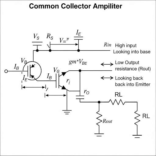
Let us see the circuit, which is the small signal equivalent circuit given here. The input voltage v, we are applying at the base and then, we do have the collector terminal which is not AC ground rather it may be having a signal called say v.
Detailed Explanation
Here, we are introduced to the common collector amplifier and its configuration. The circuit involves applying an input voltage at the base terminal while the collector remains under a signal condition rather than being grounded. This setup is essential as it signifies a key difference from previous circuit analyses where the collector terminal was treated as an AC ground.
Examples & Analogies
Think of the common collector amplifier as a control system, where applying energy at one point (the base) can effectively manage and modify the output signal (the collector), showing the impact of signal changes in more complex systems.
Current Flow and KCL Application
Chapter 2 of 7
🔒 Unlock Audio Chapter
Sign up and enroll to access the full audio experience
Chapter Content
We can say that the current flow after reaching to the emitter whether it is branching to the active device or through this R, finally, they are converging to the ground and we can say that this is also same as the base current ib.
Detailed Explanation
This chunk emphasizes the current flow from the emitter to the ground and its relationship with the base current. Understanding that the modified current paths affect how the whole circuit operates provides insight into Kirchoff's Current Law (KCL), which states that total current entering a junction must equal the total current leaving.
Examples & Analogies
Imagine a water distribution system where the water (current) reaching a junction can split off into different pipes but must eventually exit out into the main drain (ground). Each stream of water corresponds to an electrical current, helping visualize how different pathways alter the flow in an electronics circuit.
Voltage Relationships and Gain Calculation
Chapter 3 of 7
🔒 Unlock Audio Chapter
Sign up and enroll to access the full audio experience
Chapter Content
So, from this relationship, between v and v that gives us the voltage gain. In fact, we can say that v = v(in)(gain).
Detailed Explanation
This section highlights how the relationships between input voltage (v(in)) and output voltage (v) help in calculating the voltage gain of the amplifier. It's clear that the interaction of the collector and emitter voltages shapes the final output, and gaining insight into this interaction informs us how effectively the circuit amplifies signals.
Examples & Analogies
Think of this relationship as a chef scaling a recipe. The amount of ingredients (input voltage) affects how many servings (output voltage) of a dish can be produced, and understanding this scaling helps ensure the dish turns out delicious and plentiful.
Input Resistance Analysis
Chapter 4 of 7
🔒 Unlock Audio Chapter
Sign up and enroll to access the full audio experience
Chapter Content
For input resistance, what we have it is if we are applying v here whatever the i it is flowing. If I get the expression of i in terms of v that gives us the corresponding input resistance.
Detailed Explanation
This part discusses how to ascertain the input resistance of the common collector amplifier. It emphasizes the relationship between the input voltage and the current flowing into the base terminal, allowing us to define the input resistance mathematically.
Examples & Analogies
Consider trying to fit different items into a box of a fixed size (input resistance) – the resistance influenced how items fit into your box (the current); thus, ensuring the box is correctly sized is essential for optimized storage (effective operation of the amplifier).
Output Resistance Analysis
Chapter 5 of 7
🔒 Unlock Audio Chapter
Sign up and enroll to access the full audio experience
Chapter Content
So, we do have the same small signal model and to know the output resistance, we have to make the signal = 0 namely base terminal we are making it AC ground.
Detailed Explanation
Here, finding the output resistance involves deactivating the input signal (setting it to zero) and simulating the circuit’s behavior. This allows us to observe how the circuit responds solely to external signals, providing insight into its impedance characteristics.
Examples & Analogies
Imagine a garden hose: when you turn off the tap, you can feel how much water (output response) is still in the hose at rest. This gives an idea of the hose's resistance to flow, similar to determining the output resistance of the circuit.
Input Capacitance Analysis
Chapter 6 of 7
🔒 Unlock Audio Chapter
Sign up and enroll to access the full audio experience
Chapter Content
So, we do have the small signal equivalent circuit, we do have the C and then, C and note that compared to our previous discussion, the voltage here it is not AC ground rather voltage it is v and v.
Detailed Explanation
This section dives into the capacitive characteristics of the circuit by analyzing the input capacitance, detailing the significance of how signals affect the terminal voltages during operational conditions.
Examples & Analogies
Think of this as a sponge soaking up water (input capacitance); the more water it absorbs (input signal), the more the overall moisture (voltage levels) increases in the environment (circuit) surrounding it.
Conclusion and Implications
Chapter 7 of 7
🔒 Unlock Audio Chapter
Sign up and enroll to access the full audio experience
Chapter Content
So, again, we are converging to the similar kind of conclusion, namely the input capacitance is low, input resistance of this circuit it is high; output resistance, it is remaining low, voltage gain it is approximately remaining 1.
Detailed Explanation
This concluding section summarizes the key findings from the analysis: the input capacitance remains low while input resistance is high, output resistance is also low, and the voltage gain is just about 1, simplifying the operational expectations of the amplifier.
Examples & Analogies
Concluding our exploration, this amplifier is akin to a highly efficient translator—while maintaining clarity (high input resistance) and simplicity (low output interaction), it ensures that the essence of the initial message (voltage gain near 1) remains intact across the communication (amplification) spectrum.
Key Concepts
-
High Input Resistance: It helps in preventing loading of previous stages.
-
Low Output Resistance: Allows better load driving capacity.
-
Voltage Gain Close to 1: Important for applications where signal strength needs to be maintained.
Examples & Applications
An audio amplifier designed using a common collector configuration can take a weak audio signal and output a stronger signal suitable for driving speakers.
In a radio receiver, a common collector amplifier may be used to buffer the signal from the antenna before it is processed further.
Memory Aids
Interactive tools to help you remember key concepts
Rhymes
In, out, high and low, collector’s gain is all aglow!
Stories
Imagine a performer on stage. They have an amplifier that raises their voice, but just enough to keep their audience engaged without overwhelming them—just like the common collector amplifier manages signal strength.
Memory Tools
Remember 'HILR' - High Input, Low Resistance.
Acronyms
HILR
High Input
Low Resistance.
Flash Cards
Glossary
- Common Collector Amplifier
An amplifier configuration that has high input impedance and low output impedance, also known as an emitter follower.
- Voltage Gain
The ratio of output voltage to input voltage in an amplifier.
- Input Resistance
The resistance presented by the amplifier at its input terminal; it should be high for effective signal handling.
- Output Resistance
The resistance at the amplifier's output; ideally low to drive loads effectively.
- Input Capacitance
The capacitance seen at the input terminal, which affects frequency response.
Reference links
Supplementary resources to enhance your learning experience.