
Input Resistance Discussion
Enroll to start learning
You’ve not yet enrolled in this course. Please enroll for free to listen to audio lessons, classroom podcasts and take practice test.
Interactive Audio Lesson
Listen to a student-teacher conversation explaining the topic in a relatable way.
Understanding Input Resistance
🔒 Unlock Audio Lesson
Sign up and enroll to listen to this audio lesson

Today, we're diving into input resistance in common collectors! Can anyone tell me what input resistance refers to in a circuit?

Isn't it the resistance seen by the input signal at the input terminals of the amplifier?
Exactly! The input resistance determines how the circuit interacts with the input signal. It's pivotal for defining the amplifier's performance. Now, let’s explore how it’s calculated.

How does the collector resistance affect the input resistance?
Good question! The collector resistance, R, has a significant impact. When we add a collector resistance, it generally increases the overall input resistance.

So, more resistance means less current for the same input voltage?
Exactly! Remember this with the acronym I.R. which stands for Input Resistance. The higher the input resistance, the better the circuit performs with high-impedance sources.
In summary, understanding input resistance helps us optimize designs for effective signal handling.
Kirchhoff’s Current Law in Amplifiers
🔒 Unlock Audio Lesson
Sign up and enroll to listen to this audio lesson

Let's apply Kirchhoff’s Current Law to this circuit. Can anyone remind me what KCL states?

KCL states that the total current entering a junction must equal the total current leaving it.
Perfect! Now, in our amplifier circuit, if we look at the emitter node, what currents can we identify?
We have the base current flowing in and the output current going out.
Exactly! Let's write the KCL equation for the emitter node. We'll find it helps us determine how the output voltage relates to the input.
Does this mean we can derive an expression for voltage gain?
Exactly! From the KCL perspective, we can express voltage gain as a ratio of output voltage to input voltage.
To recap, KCL is essential for our understanding of current flow and helps derive critical expressions for circuit analysis.
Voltage Gain Calculation
🔒 Unlock Audio Lesson
Sign up and enroll to listen to this audio lesson
Now let’s focus on voltage gain. Who remembers how voltage gain is defined?
Is it the ratio of the output voltage to the input voltage?
That's right! And what do we know about the impact of collector resistance on this voltage gain?
I think the voltage gain tends to approach 1 when the load resistance is significant.
Exactly! This means our amplifier functions effectively as a buffer. Remember, G.A.I.N. which stands for Gain Approaches Ingress Neatly.
So, a common collector amplifier effectively maintains the input signal?
Yes, that’s the beauty of it! To summarize, voltage gain is crucial for determining our amplifier's efficiency, especially with the right resistive loads.
Effects of Resistance Configuration
🔒 Unlock Audio Lesson
Sign up and enroll to listen to this audio lesson
Finally, let’s explore how different resistance configurations affect performance. Why is it important to consider R connected at the collector?
Because it can alter both input and output impedance!
Yes! This setup helps us maximize input resistance while keeping the output resistance manageable. Who can express this impact mathematically?
I think we can represent it with the equations we've discussed earlier!
Correct! By using the equations, we can predict the circuit's behavior with varying resistance. This is crucial for optimizing circuit designs.
So the choice of resistance impacts not only the current but also the whole performance of the amplifier?
Exactly! Everything in circuits interrelates. To wrap up, understanding resistance configuration is vital in achieving desired amplifier behavior.
Introduction & Overview
Read summaries of the section's main ideas at different levels of detail.
Quick Overview
Standard
In this section, the input resistance of common collector amplifiers is analyzed, detailing the relationships between input voltage, output voltage, and the effects of collector resistance. Additionally, the implications for overall circuit impedance and voltage gain are discussed.
Detailed
Input Resistance Discussion
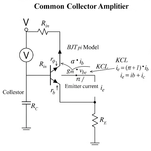
This section emphasizes the calculation and significance of input resistance in common collector amplifiers, specifically examining the relationship between base current and voltage. The small-signal equivalent circuit is referenced repeatedly, allowing for thorough analysis of how current flows through the circuit components, particularly the connected resistances.
The key equations derived in the section illustrate the linkage of the input voltage to the resulting output current through the resistance values present in the circuit. Specific focus is placed on how the collector resistance (R) impacts not only the output voltage but also input resistance and overall voltage gain.
Furthermore, the analysis draws on Kirchhoff’s Current Law (KCL) to explain the current flow at the emitter node, comparing base current and feedback currents from the active device, establishing relationships that yield the voltage gain between input and output voltages.
Through iterative discussions on these topics, students gain insights into the effects of different parameters on input impedance, output resistance, and input capacitance. The relevance of these factors in designing analog circuits is underscored, making the discussion vital for a deeper understanding of electronic designs.
Youtube Videos

Audio Book
Dive deep into the subject with an immersive audiobook experience.
Understanding Input Resistance
Chapter 1 of 4
🔒 Unlock Audio Chapter
Sign up and enroll to access the full audio experience
Chapter Content
So, let us concentrate on the input resistance and here, we do have the same small signal equivalent circuit and for input resistance, what we have it is if we are applying v here in whatever the i it is flowing. If I get the expression of i in terms of v that gives us the corresponding input resistance. So, R it is ; whereas, i , it is the base terminal current in and base terminal current is .
Detailed Explanation
In this chunk, we are discussing how to determine the input resistance of the circuit. When a voltage (v) is applied at the base terminal, the current (i) flowing through the base is measured. By finding the relationship between the applied voltage and the flowing current, we can calculate the input resistance. This is crucial in amplifier design since it affects how the amplifier interacts with the previous stage.
Examples & Analogies
Imagine a water pipe system where the pressure of the water corresponds to the voltage (v) and the flow rate corresponds to the current (i). The input resistance can be thought of as the width of the pipe; a narrow pipe (high resistance) restricts flow, while a wide pipe (low resistance) allows more water to pass through. Just like in our circuit, if the pipe (input resistance) is too restrictive, it will limit the effectiveness of the entire system.
Calculating Input Resistance
Chapter 2 of 4
🔒 Unlock Audio Chapter
Sign up and enroll to access the full audio experience
Chapter Content
Now, probably in you can rearrange this equation namely, we can write in this form . So, expression of this which is the voltage gain, we already have seen and that is essentially this part. So, if I make (1 ‒ this part), what will be getting here in the denominator it is r .
Detailed Explanation
We can manipulate the relationship we have between voltage gain and current to derive the input resistance formula. By rearranging the existing equations, we can isolate the terms so that we can see how they contribute to the calculation of input resistance. The input resistance will include the parameter r which is the resistance observed in the circuit, expressed as part of the overall relationship.
Examples & Analogies
Think of it like a recipe where you rearrange the ingredients to see how much of each is required to make the best dish. In our case, the 'ingredients' are the various resistances in play, and we are figuring out how they collectively influence the input resistance of the circuit, just as the quantities of ingredients influence the final taste of the dish.
Impact of Additional Resistance
Chapter 3 of 4
🔒 Unlock Audio Chapter
Sign up and enroll to access the full audio experience
Chapter Content
So, as a result input resistance what we can get it is this only. So, here we are just summarizing that. Input resistance is in series with R in series with r and then, the active device contribution.
Detailed Explanation
In this segment, we summarize how the input resistance is affected by various components in the circuit. We point out that the total input resistance is a combination of external factors (like Р and r) and the inherent characteristics of the active device. Adding components in series increases the overall input resistance, which is beneficial because it makes the amplifier less loading on the previous stage.
Examples & Analogies
Consider a concert hall where every extra row of seats (R) added increases the distance from the stage to the audience (input resistance). The more rows you add, the more complex it becomes for performers to engage directly with attendees, just as higher input resistance affects how the amplifier interacts with the input source.
Further Analysis of Input Resistance
Chapter 4 of 4
🔒 Unlock Audio Chapter
Sign up and enroll to access the full audio experience
Chapter Content
So, the effect of non-zero value of this R, it is increasing this resistance even higher. So, anyway that is in our favour considering the required input port characteristic. So, we have seen the voltage gain, we have seen the input resistance.
Detailed Explanation
We observe that adding a non-zero value of resistance (R) increases the input resistance, which plays to our advantage when designing amplifiers. A high input resistance is often desirable for amplifiers to ensure they do not load down the preceding stages. By analyzing the interplay of these elements, we can ensure an optimal design tailored to actual requirements.
Examples & Analogies
This scenario can be likened to fine-tuning a radio. When you adjust the antenna (adding resistance), you improve reception quality. The higher input resistance ensures the signal stays strong, much like ensuring clarity in radio frequency reception. You've optimized the circuit to receive the best performance without interference.
Key Concepts
-
Input Resistance: The resistance that an input signal encounters in an amplifier.
-
Voltage Gain: A crucial metric in understanding amplifier behavior, defined as output voltage over input voltage.
-
Current Flow: Understanding how current enters and exits nodes in a circuit is essential for predictions about circuit behavior.
-
Collective Impedance Effects: The combined effect of various resistances in a circuit impacts input and output characteristics.
Examples & Applications
When a 1kΩ collector resistor is connected to a common collector amplifier, the input resistance can increase, making it more suitable for high-impedance sources.
In a practical application, using a common collector amplifier with high input resistance allows for efficient signal buffering with minimal signal loss.
Memory Aids
Interactive tools to help you remember key concepts
Rhymes
In a collector so bright and fine, high resistance means less decline.
Stories
Imagine an eager student (the input voltage) trying to enter a classroom (the amplifier). The fewer obstacles (resistances), the easier it is for the student to get in and learn (signal amplification).
Memory Tools
I.R. – Input Resistance for best reception!
Acronyms
G.A.I.N. – Gain Approaches Ingress Neatly.
Flash Cards
Glossary
- Input Resistance
The resistance faced by the input signal at the input terminals of the circuit.
- Voltage Gain
The ratio of output voltage to input voltage in an amplifier circuit.
- Output Resistance
The resistance that an output load sees when connected to a circuit.
- Kirchhoff’s Current Law (KCL)
A law stating that the total current entering a junction equals the total current leaving that junction.
- Collector Resistance (R)
Resistance connected to the collector terminal that impacts the current flow and voltages in an amplifier.
Reference links
Supplementary resources to enhance your learning experience.