
Analog Electronic Circuits
Enroll to start learning
You’ve not yet enrolled in this course. Please enroll for free to listen to audio lessons, classroom podcasts and take practice test.
Interactive Audio Lesson
Listen to a student-teacher conversation explaining the topic in a relatable way.
Common Collector Amplifier Analysis
🔒 Unlock Audio Lesson
Sign up and enroll to listen to this audio lesson

Today, we’ll discuss the Common Collector Amplifier. What happens at the collector terminal when we apply a base voltage? Can anyone summarize?

The collector has a signal, and the input voltage is applied to the base.
Exactly! This configuration is crucial for voltage amplification. Let’s refer to 'v_c' for the collector voltage. Remember, it’s not AC ground. What does this imply for our current flow?

It means we have a non-zero value of 'v_c', which influences our base current 'i_b'.
Correct! The flow of current at the emitter can be expressed in terms of the collector current and base current. The voltage gain approaches 1 under certain conditions, meaning we retain the input signal quite effectively. Can anyone tell me why this is beneficial?

It preserves the characteristics of the original signal while providing amplification!
Well stated! High input impedance is generally desirable in these amplifiers. A quick mnemonic for today’s session: 'COMPLETE - Collector Offers Maximum Preservation of The Existing input'.
To wrap up, we established that the Common Collector Amplifier retains voltage while ensuring high input impedance.
Input Resistance
🔒 Unlock Audio Lesson
Sign up and enroll to listen to this audio lesson

Moving on to input resistance, can anyone explain how we calculate it?

We express 'i' based on the input voltage 'v_in'? I think that gives us input resistance.
Exactly! And the presence of 'R_c' plays a critical role here. What happens to the resistance when we connect 'R_c'?
It increases the input resistance even higher, making it more suitable for our applications.
Precisely! This increase in resistance aids circuit behavior. Remember the acronym 'HI – High Input' for recalling input resistance. Why is this essential for our designs?
A higher input resistance ensures less loading effect on previous stages of circuits!
Great answer! So let’s summarize the key points on input resistance before we proceed.
Output Resistance
🔒 Unlock Audio Lesson
Sign up and enroll to listen to this audio lesson
Next, let’s delve into output resistance. How do we typically assess it in a small signal model?
We set the base terminal at AC ground and observe the output current flow from 'v_x'!
Correct! The simplifications allow us to understand how this affects overall functionality. Can you describe how this output resistance is affected by 'R_c'?
The output resistance typically remains low, dominated by 'R_c' and the active device!
Well articulated! Lowe output resistance facilitates better signal transfer, making design more effective. Remember 'LO - Low Output'. What does this mean for practical applications?
It improves efficiency and reduces voltage drop across the output!
Exactly! Let’s summarize these points on output resistance succinctly.
Input Capacitance
🔒 Unlock Audio Lesson
Sign up and enroll to listen to this audio lesson
Finally, let’s explore input capacitance. Why is it important to assess this when designing amplifiers?
It can impact the frequency response and stability of the amplifier circuit!
Correct! The contribution of capacitance to signal performance can’t be overlooked. How does the Miller effect play into this?
It multiplies the input capacitance, effectively increasing it under certain conditions.
Precisely! An important takeaway is that C_in approaches C_gs for practical use. Remember the phrase 'CAPACITY INCREASES, INCREMENT IN CAPACITANCE'.
That’s a helpful way to remember!
Great! To summarize, we analyzed input capacitance and its implications on performance, especially with the Miller effect.
Introduction & Overview
Read summaries of the section's main ideas at different levels of detail.
Quick Overview
Standard
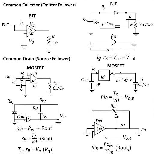
The section provides an in-depth look at Common Collector and Common Drain amplifiers, focusing on their equivalent circuits, voltage gain equations, and effects of resistances on input/output characteristics. Key parameters are analyzed to enhance understanding of these electronic circuits in practical applications.
Detailed
Analog Electronic Circuits - Detailed Summary
Overview
In this section, the intricacies of Common Collector and Common Drain amplifiers are analyzed, specifically focusing on their small signal equivalent circuits. The discussion includes how various circuit parameters such as voltage gain, input/output resistance, and input capacitance affect the performance of these amplifiers.
Key Points Covered
Common Collector Amplifier Analysis
- Input Voltage and Collector Signal: The analysis begins by applying an input voltage at the base and observing the collector terminal with a signal.
- Current Relationships: A discussion of the current flowing through the circuit and its connection to base current is presented. This includes how currents interact at the emitter node using Kirchhoff's Current Law (KCL).
- Voltage Gain Equation: The relationship between output voltage and input voltage is established, demonstrating how voltage gain approaches unity under certain conditions.
Input Resistance
- Calculating Input Resistance: The derivation of input resistance using the base terminal current is explained. The effect of connected resistances is analyzed to illustrate their influence on overall resistance.
- Effect of Input Resistance: A high input resistance is favorable for circuit applications, which is emphasized throughout the discussion.
Output Resistance
- Determining Output Resistance: The section elaborates on how output resistance is calculated, especially when observing the circuit in a particular state (AC ground at base terminal).
- Output Resistance Approximation: It is shown that the output resistance typically is very low, primarily dictated by specific circuit elements, with approximate values provided.
Input Capacitance
- Capacitance Analysis: The analysis extends to input capacitance, with emphasis on how capacitance behaves with regards to the voltage gain. The influence of Miller effects on capacitance is a critical topic.
- Final Approximation: A derived relationship indicates that input capacitance tends to remain low relative to requirements in circuit design.
Through meticulous analysis of these elements, the section builds a comprehensive understanding of the characteristics and behaviors of Common Collector and Common Drain amplifiers, vital for advanced electronics and communication engineering.
Youtube Videos

Audio Book
Dive deep into the subject with an immersive audiobook experience.
Introduction to Common Collector Amplifiers
Chapter 1 of 9
🔒 Unlock Audio Chapter
Sign up and enroll to access the full audio experience
Chapter Content
Yeah, welcome back after the short break and we are discussing about the Common Collector Amplifier, considering the resistance R connected in the collector terminal in between collector and supply voltage Vdd.
Detailed Explanation
In this section, we reintroduced the topic of the Common Collector Amplifier. This amplifier configuration is characterized by a resistance, R, connected between the collector terminal and the power supply (Vdd). It's crucial to understand how the resistor influences the operation and characteristics of the amplifier.
Examples & Analogies
Think of a Common Collector Amplifier as a water pipe system. The resistance R is like a valve that controls how much water can flow through. The more resistance (like a more restrictive valve), the less water (or current) can flow, impacting the overall functionality of the system.
Understanding Small Signal Equivalent Circuit
Chapter 2 of 9
🔒 Unlock Audio Chapter
Sign up and enroll to access the full audio experience
Chapter Content
So, let us see the circuit, which is the small signal equivalent circuit given here. The input voltage vin is applied at the base and then, we do have the collector terminal which is not AC ground rather it may be having a signal called say vc.
Detailed Explanation
We introduced the small signal equivalent circuit, which is crucial for analyzing the amplifier's behavior with small input signals. The input voltage vin is applied to the base of the transistor in the circuit, and the collector terminal is not at AC ground; instead, it has a signal vc. This setup enables us to analyze how the small variations in input affect the output.
Examples & Analogies
Imagine you're trying to listen to someone talk in a noisy room. The small signal equivalent circuit would represent your listening position (input) while the noise level in the room represents the signal at the collector. Understanding these dynamics helps you tune out the noise (background signals) and focus on the actual conversation (output).
Current Flow Analysis
Chapter 3 of 9
🔒 Unlock Audio Chapter
Sign up and enroll to access the full audio experience
Chapter Content
So, we can say that the current flow after reaching to the emitter whether it is branching to the active device or through this Rc; finally, they are converging to the ground and we can say that this is also same as the base current ib.
Detailed Explanation
This chunk focuses on how current flows in the circuit. After passing through the emitter, the current may either go through the active device or through the resistor Rc before converging to ground. It's important to note that this flow is equivalent to the base current ib, emphasizing that the behavior of currents in the circuit directly affects the amplifier's performance.
Examples & Analogies
Consider the current flow like water through different paths in a garden. Some water (current) flows directly to the flower (active device), while some may divert through a small stream (Rc) before eventually reaching the rest of the garden (ground). Understanding these paths can help gardeners manage water use effectively.
Applying Kirchhoff's Current Law
Chapter 4 of 9
🔒 Unlock Audio Chapter
Sign up and enroll to access the full audio experience
Chapter Content
So, now if I apply KCL at the emitter node, what we are getting? Here, it is current flowing through this Rc which is equal to the summation of the two currents; one is the base current and other is the current through the active device.
Detailed Explanation
We applied Kirchhoff's Current Law (KCL) at the emitter node to assess the relationship between the currents in the circuit. This principle states that the sum of currents entering a junction must equal the sum of currents leaving. In this scenario, the current flowing through the resistor Rc equals the combined currents of the base and the active device, allowing us to derive important equations for our analysis.
Examples & Analogies
Imagine a traffic intersection where the total number of cars entering must equal the total number leaving. If a certain number heads onto a side street (Rc), that number must equal the cars taking the main road (base current) and those parking nearby (current through the active device). This analogy helps us visualize the flow of current in the circuit.
Output Voltage Relationships
Chapter 5 of 9
🔒 Unlock Audio Chapter
Sign up and enroll to access the full audio experience
Chapter Content
Now, this expression of this vc, it is in terms of vin and other variables. This equation can be utilized to replace this vc to get an expression which involves only vin.
Detailed Explanation
This section discusses the relationship of output voltage (vc) in terms of the input voltage (vin) and other parameters. By using our previous equations, we can simplify our analysis and express vc purely in terms of vin. This is a critical step in determining the voltage gain of the amplifier, which tells us how much the input signal gets amplified.
Examples & Analogies
Think of this as creating a recipe. By knowing the right ratios of ingredients (vin, other parameters), we can figure out the quantity of the finished dish (vc). This allows cooks (engineers) to ensure consistency in flavor (amplification) every time they prepare the meal.
Voltage Gain Assessment
Chapter 6 of 9
🔒 Unlock Audio Chapter
Sign up and enroll to access the full audio experience
Chapter Content
From this relationship, between vo and vin that gives us the voltage gain. In fact, we can say that vo = vin multiplied by some factor.
Detailed Explanation
We concluded with the assessment of voltage gain, a measure of how effectively the amplifier increases the input voltage to produce a larger output voltage. The voltage gain can be expressed as the ratio of vo (output voltage) to vin (input voltage), providing invaluable insight into the performance of the amplifier.
Examples & Analogies
Think of voltage gain like the efficiency of a speaker. If you feed a small sound into it (vin), and it produces a much louder sound (vo), the ratio of loudness represents the voltage gain. Understanding this helps sound engineers ensure that the audio amplification system functions effectively.
Input Resistance Considerations
Chapter 7 of 9
🔒 Unlock Audio Chapter
Sign up and enroll to access the full audio experience
Chapter Content
So, let us concentrate on the input resistance and here, we do have the same small signal equivalent circuit and for input resistance, what we have it is if we are applying vin here whatever the iin it is flowing. If I get the expression of iin in terms of vin that gives us the corresponding input resistance.
Detailed Explanation
In this section, we focused on calculating the input resistance of the amplifier. By applying a known input voltage, we measured the input current (iin) and developed an expression that correlates both, allowing us to determine how resistant the circuit is to incoming signals. This characteristic is crucial for its compatibility with different input sources.
Examples & Analogies
Consider the input resistance as the thickness of a hose used to transport water. A thicker hose (high input resistance) allows more water (signals) to flow in smoothly, while a thinner one (low input resistance) might cause restrictions, impacting overall efficiency.
Output Resistance Analysis
Chapter 8 of 9
🔒 Unlock Audio Chapter
Sign up and enroll to access the full audio experience
Chapter Content
So, if you see the output resistance. So, we do have the same small signal model and to know the output resistance, we have to make the signal = 0 namely base terminal we are making it AC ground.
Detailed Explanation
To determine the output resistance, we analyzed the small signal model under the condition where the input signal is considered to be zero (AC ground). This analysis is crucial to understanding how the amplifier behaves when connected to a load, directly affecting performance.
Examples & Analogies
Imagine this as assessing how much pressure a water system can withstand when there’s no actual flow (output signal). By closing the valves (making AC ground), we can understand the system's resistance to pressure, which is similar to measuring output resistance in electronic circuits.
Final Analysis and Conclusion
Chapter 9 of 9
🔒 Unlock Audio Chapter
Sign up and enroll to access the full audio experience
Chapter Content
So, let us summarize this analysis for a common collector circuit considering this collector resistance. Similar kind of things we can do for the MOS counterpart.
Detailed Explanation
Finally, we wrapped up the analysis of the Common Collector amplifier, emphasizing the influence of collector resistance on circuit behavior. We noted that similar principles could apply to MOS amplifiers, indicating the universality of these concepts across different types of semiconductor devices.
Examples & Analogies
This conclusion is akin to summarizing a series of training sessions for athletes. Insights from one sport could apply to others, and understanding these foundational principles can guide training and performance improvements across various physical activities.
Key Concepts
-
Voltage Gain: Defines how much an amplifier increases the input signal voltage.
-
Input Resistance: Affects how much the amplifier loads previous circuit stages.
-
Output Resistance: Determines how effectively the amplifier can drive loads.
-
Miller Effect: Illustrates how input capacitance increases due to feedback.
Examples & Applications
In designing a Common Collector Amplifier, a resistor connected to the collector influences the output voltage.
In a typical amplifier setup, low output resistance ensures that there’s minimal voltage drop across the amplifier's output due to load.
Memory Aids
Interactive tools to help you remember key concepts
Rhymes
For every input high, output flies, keep the resistance low, that's how amplifiers grow!
Stories
Imagine a librarian (the Common Collector) who helps borrowers keep their books (voltage) without losing volume. This depicts how the circuit buffer functions.
Memory Tools
Remember 'VIC' - Voltage, Input, Current for the features of Common Collector amplifiers.
Acronyms
COVI - Collector offers voltage increase.
Flash Cards
Glossary
- Common Collector Amplifier
An amplifier configuration that provides voltage buffering with high input impedance and low output impedance.
- Voltage Gain
The ratio of output voltage to input voltage in an amplifier, indicating its amplification power.
- Input Resistance
The resistance seen by the input signal, influencing loading effects in circuits.
- Output Resistance
The resistance encountered by the output signal, affecting signal transfer.
- Miller Effect
The apparent increase in capacitance observed in feedback systems, impacting bandwidth.
Reference links
Supplementary resources to enhance your learning experience.