
Common Drain Amplifier Analysis
Enroll to start learning
You’ve not yet enrolled in this course. Please enroll for free to listen to audio lessons, classroom podcasts and take practice test.
Interactive Audio Lesson
Listen to a student-teacher conversation explaining the topic in a relatable way.
Understanding Voltage Gain in Common Drain Amplifiers
🔒 Unlock Audio Lesson
Sign up and enroll to listen to this audio lesson

Today, we'll dive into the voltage gain of common drain amplifiers. Can anyone tell me what we mean by voltage gain?

I think it's just the ratio of the output voltage to the input voltage, right?
Exactly! The voltage gain is defined as Vout over Vin. Now, in a common drain amplifier, we find that the voltage gain is approximately 1. Why do you think that happens?

Maybe because the output is closely following the input?
That's correct! It behaves like a buffer. Let's remember this with the acronym 'VGA' - Voltage Gain Approximation!

So, does that mean it doesn’t amplify the signal?
Good question! While it does not amplify in terms of gain, it is crucial for buffering signals to maintain levels. Summarizing this session, common drain amplifiers have a voltage gain close to 1, acting as buffer circuits.
Input Resistance in Common Drain Amplifiers
🔒 Unlock Audio Lesson
Sign up and enroll to listen to this audio lesson

Next, let’s discuss input resistance. Why is input resistance important for amplifiers?

I think it helps to ensure that the amplifier doesn’t load down the previous stage.
Absolutely! For common drain amplifiers, the input resistance can be very high, thanks to the characteristics of the MOSFET. Can anyone help me recall how we calculate it?
We look at the base current and its relationship to input voltage, right?
Correct! By examining the current flow, we calculate that high input resistance aids in preserving signal integrity. Let’s remember this with the mnemonic 'I RISE' - Input Resistance In Signal Enhancement!
So, higher input resistance is better then?
Yes! Higher input resistance is always beneficial in amplifier design. In summary, common drain amplifiers exhibit high input resistance, promoting better signal transfer without loading effects.
Output Resistance in Common Drain Amplifiers
🔒 Unlock Audio Lesson
Sign up and enroll to listen to this audio lesson
Now, onto output resistance. Why do we need to measure output resistance in amplifiers?
It determines how well the amplifier drives loads, right?
Exactly! If an amplifier has low output resistance, it can effectively deliver power to a load. For common drain amplifiers, we establish that the output resistance is typically quite small. What factors contribute to that?
The internal resistance of the MOSFET?
Correct! A low output resistance enhances load-driving capability. Use the phrase 'Low Resistance = High Drive' to help you remember this point!
So, it’s good to have low output resistance?
Definitely! Low output resistance allows the amp to drive loads effectively. To summarize today’s discussion, the output resistance in common drain amplifiers is low, facilitating better power transfer to connected loads.
Input Capacitance in Common Drain Amplifiers
🔒 Unlock Audio Lesson
Sign up and enroll to listen to this audio lesson
Finally, let’s discuss input capacitance. Can anyone explain what input capacitance means in context?
It's the capacitance seen by the input, affecting how signals come into the amplifier.
Exactly! Input capacitance influences the frequency response and gain stability. In common drain amplifiers, we see this influenced by the Miller effect. How so?
Because the gain has an indirect effect on the capacitance, right?
That's right! The input capacitance can be approximated under certain assumptions, leading us to understand that common drain amplifiers maintain low input capacitance for optimal performance. Use the acronym 'CAP' - Common And Small Capacitivities!
So, how do we actually calculate it?
The calculation involves considering both capacitances and their ratio to voltage gains. In summary, input capacitance in common drain amplifiers is low, and careful calculations reveal its effect on overall performance.
Introduction & Overview
Read summaries of the section's main ideas at different levels of detail.
Quick Overview
Standard
In this section, the analysis of common drain amplifiers is presented with a focus on how parameters such as voltage gain, input resistance, output resistance, and input capacitance are affected by various circuit configurations. The significance of these parameters and their implications for amplifier design is underscored.
Detailed
Detailed Summary
The section on Common Drain Amplifier Analysis explains the operation and characteristics of common drain amplifiers, emphasizing key electrical parameters. Initially, the voltage gain is evaluated by establishing the relationship between the output and input voltages, revealing that the gain approximates to 1 under certain conditions. The role of collector or drain resistance is discussed, noting that it significantly affects the output performance. The input resistance is computed by analyzing current flow at the base terminal and considering the impacts of various connected resistances, such as the emitter resistor in BJTs and the source resistor in MOSFETs.
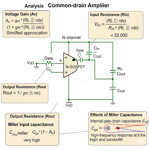
The section further explores output resistance by setting the input to AC ground and analyzing the circuit under that condition, leading to a determination that the output resistance is typically in the order of small signal parameters. Lastly, the concept of input capacitance is revisited, recognizing how Miller effect influences these capacitative parameters. Through this analysis, a blueprint is provided for understanding both common collector and common drain configurations, facilitating an understanding that can be useful for further study in analog electronics.
Youtube Videos

Audio Book
Dive deep into the subject with an immersive audiobook experience.
Introduction to Common Drain Amplifier
Chapter 1 of 5
🔒 Unlock Audio Chapter
Sign up and enroll to access the full audio experience
Chapter Content
So, we do have this resistance connected to the drain terminal and then, we do have the R coming in the small signal equivalent circuit and then, we do not have any r here. So, rather if I say that whatever the previous analysis we have done, if I consider the r in those equations approximately going to be very high. Then, we can get the equation for the common drain.
Detailed Explanation
A common drain amplifier, also known as a source follower, is characterized by having a load resistor, denoted as R, connected to its drain terminal. In this setup, we analyze the behavior in terms of small signal equivalent circuits. The absence of the resistance r, which represents the intrinsic device resistance, indicates that we can assume high values for the intrinsic parameters involved, simplifying our calculations for common drain analysis.
Examples & Analogies
Think of a common drain amplifier like a water hose. The water (current) flows through the hose without encountering much obstruction (resistance), thanks to the way it's set up, allowing for a smooth and efficient flow.
Voltage Gain in Common Drain Amplifier
Chapter 2 of 5
🔒 Unlock Audio Chapter
Sign up and enroll to access the full audio experience
Chapter Content
So, if I say that expression of the v can be obtained by considering this equation which you already have derived and that can be done by making this is going to be very high and this is going to be very high. Namely, in the numerator if I keep this term and in the denominator if I keep this term and this term and then, if I pull out this r and if I cancel it what will be getting here it is v × g r in the numerator and in the denominator, we will be having 1 + g r .
Detailed Explanation
The voltage gain of a common drain amplifier is derived from the relationship between the output and input voltages. By considering the effects of very high values for certain parameters, we can derive a simplified gain expression. The voltage gain is approximately equal to (v × g r) / (1 + g r). This shows how the input voltage is scaled at the output, allowing engineers to design circuits that provide specific amplification levels.
Examples & Analogies
Imagine you’re turning the volume knob on a speaker. The position of the knob (input voltage) affects how loudly the speaker plays (output voltage). The relationship between these variables defines how much amplification you experience when you turn the knob.
Output Resistance Analysis
Chapter 3 of 5
🔒 Unlock Audio Chapter
Sign up and enroll to access the full audio experience
Chapter Content
Now, if I consider say this part, earlier we have seen that if I want to know the resistance or impedance at the output terminal and if I stimulate this circuit by a voltage source called v and then, if I consider the corresponding i and then, if I take the ratio of this two that is supposed to be given as the resistance coming from this circuit.
Detailed Explanation
To evaluate the output resistance of the common drain amplifier, we approximate the output impedance by applying a test voltage and measuring the corresponding current. The resulting ratio gives us the output resistance, illustrating how much the output impedance impacts circuit performance, particularly concerning loading effects and signal integrity.
Examples & Analogies
Consider output resistance like the size of the exit ramp on a highway. A wider ramp (lower resistance) allows more vehicles (signals) to exit smoothly without causing congestion (distortion), while a narrow ramp (high resistance) might slow down the flow of traffic.
Input Capacitance Considerations
Chapter 4 of 5
🔒 Unlock Audio Chapter
Sign up and enroll to access the full audio experience
Chapter Content
So, to get the input capacitance C , we do have the contribution coming from C earlier in common collector it was C . So, we need to replace this by C . So, likewise here also we are having now it is C ; earlier in common collector circuit, it was C .
Detailed Explanation
Input capacitance in the common drain amplifier is crucial for determining how the amplifier responds to varying frequencies. By analyzing how different capacitive elements contribute to the total input capacitance, engineers can design circuits optimized for signal integrity and performance. In comparison to common collectors, these values become pivotal in predicting circuit behavior.
Examples & Analogies
Think of input capacitance like the fan speed in a room. A faster fan (lower capacitance) can quickly circulate air (signals) effectively through the room compared to a slower fan (higher capacitance) that might take longer to distribute air evenly.
Final Observations on Circuit Performance
Chapter 5 of 5
🔒 Unlock Audio Chapter
Sign up and enroll to access the full audio experience
Chapter Content
So, then you can say that for common drain even if I consider R , then the basic required property of the buffer, it remains the same.
Detailed Explanation
In conclusion, despite the complexities involving various resistors and capacitive elements, the fundamental properties of the common drain amplifier – such as high input resistance, low output resistance, and a voltage gain close to unity – remain intact. This highlights the amplifier's effectiveness as a buffer in electronic circuits.
Examples & Analogies
Think of it like a sponge (the common drain amplifier) that can soak up water (input signals) and release it smoothly with minimal resistance, ensuring that the water flow is consistent, without losing much as it passes through.
Key Concepts
-
Voltage Gain: The ratio of output to input voltage, which can be close to 1 for common drain amplifiers.
-
High Input Resistance: Essential to avoid loading effects and maintain signal integrity.
-
Low Output Resistance: Enhances the ability to drive loads effectively.
-
Input Capacitance: Must be considered as it impacts the amplifier’s frequency response.
-
Miller Effect: The influence of feedback on the input capacitance seen by the amplifier.
Examples & Applications
In a common drain amplifier configuration with a source resistance of 1kΩ and a load of 10kΩ, the input voltage may follow the output voltage closely with minimal loss.
A circuit with a MOSFET configured in common drain mode will display high input resistance, allowing a weak signal to be amplified without significant degradation.
Memory Aids
Interactive tools to help you remember key concepts
Rhymes
Gain that’s near to one, any output’s just for fun!
Stories
Imagine you’re at a party. The mic is a common drain amplifier, ensuring your voice—output—follows your words—input—perfectly!
Memory Tools
Use 'RIC' to remember: Resistance Increases = Capacitive effects!
Acronyms
'LOW' for low output resistance
Load Output Works!
Flash Cards
Glossary
- Voltage Gain
The ratio of the output voltage to the input voltage in an amplifier.
- Input Resistance
The resistance looking into the amplifier's input; high values are preferred to avoid loading effects.
- Output Resistance
The resistance looking into the amplifier's output, influencing how well it can drive a load.
- Input Capacitance
The capacitance seen at the input of the amplifier that can affect its frequency response.
- Miller Effect
An amplification of input capacitance due to feedback in amplifiers, significantly influencing performance.
Reference links
Supplementary resources to enhance your learning experience.