
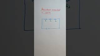
Resistors in Series
Enroll to start learning
You’ve not yet enrolled in this course. Please enroll for free to listen to audio lessons, classroom podcasts and take practice test.
Interactive Audio Lesson
Listen to a student-teacher conversation explaining the topic in a relatable way.
Understanding Series Circuits
🔒 Unlock Audio Lesson
Sign up and enroll to listen to this audio lesson

Today, we are going to learn about series circuits, specifically how resistors behave when they are connected in series. Who can tell me what happens to the current in such a circuit?

I think the current stays the same throughout the circuit.
Exactly! The current remains constant across each resistor connected in series. This is important because it helps us understand how the resistors affect the total current.

Does that mean the voltage can change across each resistor?
Yes, that’s correct! The voltage drop can vary from one resistor to another, depending on their resistance values. Would someone like to explain how we can find the total resistance in a series?

I think we just add them up: R_total = R_1 + R_2 + R_3.
Exactly! The total resistance is the sum of all individual resistances. Remember this with the phrase 'add them up!'
To summarize, in a series circuit, the current is constant, and the total resistance is simply the sum of all resistors.
Voltage and Current in Series Circuits
🔒 Unlock Audio Lesson
Sign up and enroll to listen to this audio lesson

Now let's dive deeper into how voltage behaves in a series circuit. If we have three resistors connected in series and we measure the voltage across the entire circuit, what do we expect to happen?

I think the total voltage is split across the resistors.
Correct! The total voltage is equal to the sum of the individual voltages across each resistor. This means V_total = V_1 + V_2 + V_3. Can anyone explain how we could measure these voltages in an experiment?
We could use a voltmeter!
Great idea! By connecting a voltmeter across each resistor, we can see how voltage is distributed based on each resistor's resistance. Remember, knowing how to properly set up measurements is crucial!
What if one of the resistors is removed? What happens then?
Excellent question! If one resistor is removed, the current will stop flowing in the entire circuit. This is known as the open circuit condition.
So, in summary: Each resistor receives a part of the total voltage, and removing any resistor in a series circuit stops the current flow.
Applying Ohm's Law in Series Circuits
🔒 Unlock Audio Lesson
Sign up and enroll to listen to this audio lesson
Let’s utilize Ohm’s Law to solve some practical problems related to series resistors. Who can remind us what Ohm’s Law states?
Ohm's Law states that V = IR.
Correct! Where V is the voltage, I is the current, and R is the resistance. Now, if we know the total voltage across our series circuit and the total resistance, how can we find the current flowing?
We can rearrange it to I = V/R.
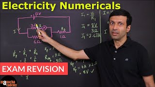
Exactly, while R_total = R_1 + R_2 + R_3. Let’s take an example. Imagine we have a 12V battery connected to resistors of 2Ω and 3Ω in series. What’s the current?
First, we find total resistance: 2Ω + 3Ω = 5Ω. So, I = 12V / 5Ω = 2.4A.
Well done! So, the current flowing through the series circuit is 2.4A, and this knowledge can help us analyze various electrical devices.
To summarize, we can calculate current by using Ohm’s Law and the total resistance in a series circuit!
Example and Application of Series Resistors
🔒 Unlock Audio Lesson
Sign up and enroll to listen to this audio lesson
Lastly, let’s discuss a practical application of series resistors. Why might we want to connect resistors in series?
To increase the total resistance in the circuit!
Correct! By increasing the resistance in the circuit, we can control the current. This is useful in devices like dimmer switches. Can anyone think of another example?
Isn’t it used in LED circuits to limit the current flowing through the LEDs?
Yes! Great observation! LEDs are sensitive to high currents, and series resistors help protect them. Before we wrap up, can anyone summarize the key points we discussed today?
We learned that in series circuits the current is constant, total resistance is the sum of the resistors, and voltage divides among them!
Fantastic summary! Keep it in mind as we move on to explore parallel circuits.
Introduction & Overview
Read summaries of the section's main ideas at different levels of detail.
Quick Overview
Standard
In circuits with resistors connected in series, the current remains constant through each resistor, while the total resistance is the sum of the individual resistances. The section illustrates key concepts through interactive activities and provides mathematical relationships derived from Ohm’s Law.
Detailed
In a series circuit, multiple resistors are connected end-to-end, causing the same current to flow through each resistor. This characteristic means that the total resistance in the circuit is equal to the sum of the individual resistances: R_total = R_1 + R_2 + R_3. Activities in the section demonstrate how the current remains unchanged regardless of its position in the circuit, and how the potential difference across the combination results in a symmetrical distribution of voltage across each resistor. By applying Ohm’s Law, we derive the total current using the equivalent resistance of the series circuit.
Youtube Videos


Audio Book
Dive deep into the subject with an immersive audiobook experience.
Current in Series
Chapter 1 of 3
🔒 Unlock Audio Chapter
Sign up and enroll to access the full audio experience
Chapter Content
What happens to the value of current when a number of resistors are connected in series in a circuit? What would be their equivalent resistance? Let us try to understand these with the help of the following activities.
Activity:
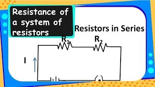
- Join three resistors of different values in series. Connect them with a battery, an ammeter and a plug key, as shown in Fig. 11.6.
- Plug the key. Note the ammeter reading.
- Change the position of the ammeter to anywhere in between the resistors. Note the ammeter reading each time.
You will observe that the value of the current in the ammeter is the same, independent of its position in the electric circuit. It means that in a series combination of resistors the current is the same in every part of the circuit or the same current through each resistor.
Detailed Explanation
When resistors are connected in series, they are arranged one after another, forming a single path for electrical flow. No matter where you measure the current using an ammeter in this series circuit, the reading remains constant. This indicates that the full current flows uniformly through each resistor, meaning the same amount of charge passes through each resistor in the same period of time. So, the principle here is that the current remains unchanged throughout a series circuit.
Examples & Analogies
Think of a series circuit like a line of people passing a ball. If one person passes the ball to the next without keeping it, every person will get the ball in turn. Regardless of who is passing it, everyone in that line is indeed passing the same ball along the same path; hence, the flow is constant.
Voltage in Series Resistors
Chapter 2 of 3
🔒 Unlock Audio Chapter
Sign up and enroll to access the full audio experience
Chapter Content
Activity:
- In Activity 11.4, insert a voltmeter across the ends X and Y of the series combination of three resistors.
- Plug the key in the circuit and note the voltmeter reading. It gives the potential difference across the series combination of resistors.
- Let it be V. Now measure the potential difference across the two terminals of the battery. Compare the two values.
- Take out the plug key and disconnect the voltmeter. Now insert the voltmeter across the ends X and P of the first resistor.
- Plug the key and measure the potential difference across the first resistor. Let it be V1. Similarly, measure the potential difference across the other two resistors, separately. Let these values be V2 and V3, respectively.
You will observe that the potential difference V is equal to the sum of potential differences V1, V2, and V3. That is the total potential difference across a combination of resistors in series is equal to the sum of potential differences across the individual resistors. That is,
V = V1 + V2 + V3.
Detailed Explanation
In a series circuit, the total voltage across the resistors is equal to the sum of the voltages across each resistor. This means that as electric current flows through the resistors, each one uses a part of the energy (voltage) supplied by the battery. By measuring the voltage across each resistor and adding them up, we find that they equal the total voltage provided by the battery. This relationship is essential for understanding how circuits manage energy.
Examples & Analogies
Imagine a set of hurdles on a track. The energy provided by the runner (battery) determines how fast they can go. Each hurdle they jump over takes away some energy (voltage) to propel them onward. If you add up all the energy 'used' for each hurdle, you'll find it matches the total energy from the runner. Hence, the hurdles cumulatively determine the flow of energy forward.
Equivalent Resistance of Series Resistors
Chapter 3 of 3
🔒 Unlock Audio Chapter
Sign up and enroll to access the full audio experience
Chapter Content
In the electric circuit, let I be the current through the circuit. The current through each resistor is also I. It is possible to replace the three resistors joined in series by an equivalent single resistor of resistance Rs, such that the potential difference V across it, and the current I through the circuit remains the same. Applying Ohm’s law to the entire circuit, we have:
- V = I Rs
On applying Ohm’s law to the three resistors separately, we further have:
- V1 = I R1
- V2 = I R2
- V3 = I R3
From Eq. (11.11),
- V = V1 + V2 + V3
- I Rs = I R1 + I R2 + I R3
Thus, simplifying gives:
- Rs = R1 + R2 + R3.
Detailed Explanation
When you're dealing with resistors in series, it’s convenient to replace them with just one equivalent resistor that behaves the same in the circuit. The equivalent resistance, denoted as Rs, is simply the sum of the individual resistances of each resistor in the series. This means if you combine a 2Ω, a 3Ω, and a 5Ω resistor in series, the equivalent resistance is R = 2 + 3 + 5 = 10Ω. This principle simplifies circuit analysis and calculations.
Examples & Analogies
Think of it like a candy shop with three different types of candy (resistors). The total amount of candy you can buy at any one time will be the sum of all candies offered. If the candy shop offers 2 types of chocolate bars (2Ω), a sweet (3Ω), and a sour candy (5Ω), the total candy available to buy in the shop (the equivalent candy) totals to 10 pieces. This means regardless of how many colors or flavors you have, the overall amount you can 'consume' is simply the sum of all.
Key Concepts
-
Current: The flow of electric charge through a conductor.
-
Voltage: The potential difference that drives current through a circuit.
-
Resistance: The opposition to current flow within a circuit.
-
Ohm's Law: The relationship governing voltage, current, and resistance in a circuit.
-
Total Resistance in Series: The total resistance is equal to the sum of individual resistances.
Examples & Applications
When resistors of 2Ω, 3Ω, and 5Ω are connected in series with a 12V battery, the total resistance is 2 + 3 + 5 = 10Ω, and the current would be calculated using Ohm's Law: I = V/R = 12V/10Ω = 1.2A.
If you have a circuit with a lamp with 20Ω and a conductor of 4Ω in series with a 6V battery, the total resistance becomes 20Ω + 4Ω = 24Ω, resulting in a current of 0.25A.
Memory Aids
Interactive tools to help you remember key concepts
Rhymes
In a series, the current does flow, it's the same, don't you know!
Stories
Imagine a train with different carriages – the same number of passengers (current) in each, moving through a long track (the total resistance being the sum of each carriage's resistance).
Memory Tools
SPLAT: Series means 'Sum' of resistances leading to 'Same' current through all components.
Acronyms
RCS
Remember
in series Circuits
Resistance adds up
and Current stays constant.
Flash Cards
Glossary
- Current
The flow of electric charge, measured in amperes (A).
- Voltage
The electric potential difference between two points, measured in volts (V).
- Resistance
The opposition to the flow of current in a conductor, measured in ohms (Ω).
- Ohm's Law
A fundamental principle stating that the voltage across a resistor is directly proportional to the current flowing through it (V = IR).
- Equivalent Resistance
The total resistance of a circuit comprising multiple resistors, can be calculated for series as R_total = R_1 + R_2 + R_3.
Reference links
Supplementary resources to enhance your learning experience.