
Modes of Operation
Enroll to start learning
You’ve not yet enrolled in this course. Please enroll for free to listen to audio lessons, classroom podcasts and take practice test.
Interactive Audio Lesson
Listen to a student-teacher conversation explaining the topic in a relatable way.
Active Mode
🔒 Unlock Audio Lesson
Sign up and enroll to listen to this audio lesson

Let's begin by discussing the Active Mode. This is where BJTs amplify signals. Can anyone tell me what it means when the transistor is in this mode?

It means the emitter-base junction is forward biased and the collector-base junction is reverse biased?
Exactly! And how does that affect current flow?

The small base current controls a larger collector current.
Great job! Remember the acronym 'ACE' for Active mode: Amplification, Control, Energy.
Cut-off Mode
🔒 Unlock Audio Lesson
Sign up and enroll to listen to this audio lesson

Now, let's talk about Cut-off Mode. What happens during this mode?

Both junctions are reverse biased, and the transistor is off.
Correct! Why is this mode important in digital circuits?

It allows us to have a clear 'off' state without any current flow.
Exactly! Think of the 'C' in 'Cut-off' as 'Current not flowing'.
Saturation Mode
🔒 Unlock Audio Lesson
Sign up and enroll to listen to this audio lesson
Let's dive into Saturation Mode now. What does it mean for a BJT to be in saturation?
Both junctions are forward biased, and the transistor is on.
Right! And what does that imply for current flow?
The transistor acts like a closed switch, allowing maximum current to flow.
Exactly! Remember, 'Saturation is like an on switch', to help you recall its function.
Inverse Active Mode
🔒 Unlock Audio Lesson
Sign up and enroll to listen to this audio lesson
Finally, let’s talk about Inverse Active Mode. Does anyone know what this mode entails?
The emitter-base junction is reverse biased while the collector-base junction is forward biased.
Correct! But why is it not commonly used?
Because it has lower performance compared to the other modes?
Exactly! Use the acronym 'I.A. Not Active' to remind you this mode is typically inactive in practical applications.
Introduction & Overview
Read summaries of the section's main ideas at different levels of detail.
Quick Overview
Standard
The Modes of Operation section explains the various operational states of BJTs, detailing Active mode for amplification, Cut-off and Saturation modes for switching, and the rarely used Inverse Active mode. Understanding these modes is essential for utilizing BJTs effectively in electronic circuits.
Detailed
Modes of Operation in BJTs
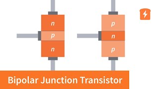
Bipolar Junction Transistors (BJTs) exhibit four distinct modes of operation that dictate their functionality in various applications. These modes are crucial for understanding how BJTs amplify signals and act as switches. Below are the primary modes:
- Active Mode: In this mode, the emitter-base junction is forward biased, while the collector-base junction is reverse biased. BJTs operate as amplifiers in this state, allowing a small base current to control a larger collector current.
- Cut-off Mode: In the cut-off state, both the emitter-base and collector-base junctions are reverse biased, effectively turning the transistor off. No current flows through the device, making it an ideal state for digital logic applications where a low (off) signal is required.
- Saturation Mode: When both junctions are forward biased, the transistor is in saturation. It behaves like a closed switch, enabling maximum current flow from the collector to the emitter. This state is useful in applications that require the transistor to function as a switch.
- Inverse Active Mode: This mode is characterized by the emitter-base junction being reverse biased and the collector-base junction forward biased. It is infrequently used in practice due to lower performance characteristics compared to the normal operation modes.
Understanding these modes allows engineers to employ BJTs effectively in various electronic applications, from signal amplification in audio equipment to switching in digital circuits.
Youtube Videos


Audio Book
Dive deep into the subject with an immersive audiobook experience.
Active Mode
Chapter 1 of 4
🔒 Unlock Audio Chapter
Sign up and enroll to access the full audio experience
Chapter Content
Region
Emitter-Base: Forward
Collector-Base: Reverse
Description: Amplifier mode
Detailed Explanation
In this mode, the emitter-base junction of the BJT is forward biased, while the collector-base junction is reverse biased. This allows the transistor to amplify signals. The forward biasing of the emitter-base junction means that current can flow easily from the emitter to the base. This, in turn, controls a larger current that can flow from the collector to the emitter, allowing for amplification of input signals.
Examples & Analogies
Think of the active mode as a water tap. When you open the tap (forward biasing), a small flow of water (current) can control a larger flood (larger current) flowing through a pipe. The tap regulates the amount flowing out, just like the base current controls the collector current.
Cut-off Mode
Chapter 2 of 4
🔒 Unlock Audio Chapter
Sign up and enroll to access the full audio experience
Chapter Content
Region
Emitter-Base: Reverse
Collector-Base: Reverse
Description: Transistor is OFF
Detailed Explanation
In this mode, both the emitter-base and collector-base junctions are reverse biased. This effectively means no current flows through the transistor, keeping it in an 'off' state. The transistor behaves like an open switch, preventing current from passing through from collector to emitter. This is useful in digital logic when the transistor is used to represent '0' or 'OFF'.
Examples & Analogies
Imagine a closed door. When the door is closed (cut-off mode), no one can enter or exit the room (no current flows). Just as you need to physically open the door to allow passage, the transistor needs to be turned on (forward bias) for current to flow.
Saturation Mode
Chapter 3 of 4
🔒 Unlock Audio Chapter
Sign up and enroll to access the full audio experience
Chapter Content
Region
Emitter-Base: Forward
Collector-Base: Forward
Description: Transistor is fully ON (switch)
Detailed Explanation
In saturation mode, both the emitter-base and collector-base junctions are forward biased. This allows maximum current to flow through the transistor, making it fully 'on'. In this state, the transistor is acting as a closed switch, enabling current to flow freely from collector to emitter. This is commonly used in switching applications where the transistor allows for the efficient passage of current.
Examples & Analogies
Picture turning on a light switch. When you flip the switch on (saturation mode), electricity flows freely, and the light bulb glows brightly. The switch (transistor) is now fully conducting, allowing maximum current to pass through.
Inverse Active Mode
Chapter 4 of 4
🔒 Unlock Audio Chapter
Sign up and enroll to access the full audio experience
Chapter Content
Region
Emitter-Base: Reverse
Collector-Base: Forward
Description: Not used in practice
Detailed Explanation
This mode involves the emitter-base junction being reverse biased and the collector-base junction being forward biased. While it describes a state where the transistor can conduct, it is not commonly used in practice because it does not effectively leverage the transistor's characteristics for amplification or switching. The performance is generally inferior and tends to lead to larger distortions.
Examples & Analogies
Think of it as trying to drive a car in reverse up a steep hill (inverse active mode). While it's technically possible, it's impractical and difficult compared to driving forward where you have better control and ease of acceleration. Thus, most engineers avoid operating transistors in this mode.
Key Concepts
-
Active Mode: BJTs amplify signals when in this mode, with the emitter-base forward biased.
-
Cut-off Mode: Represents the OFF state of the transistor, with no current flowing.
-
Saturation Mode: The transistor acts as a switch, allowing maximum current to flow.
-
Inverse Active Mode: Rarely utilized state, having different biasing conditions.
Examples & Applications
In Active Mode, a small audio signal from a microphone can be amplified to drive a large speaker.
In Cut-off Mode, a digital circuit stops current to represent a logical '0'.
In Saturation Mode, a relay is activated by ensuring enough current flows through the transistor.
The Inverse Active Mode could theoretically allow a transistor to amplify signals but is inefficient.
Memory Aids
Interactive tools to help you remember key concepts
Rhymes
In Active mode, the signal is bright, Cut-off means no current in sight.
Stories
Imagine a busy switchboard, 'Active' is where the operator amplifies calls. In 'Cut-off,' the switchboard is quiet, as no calls come in.
Memory Tools
A.C.S.I - Active, Cut-off, Saturation, Inverse Active to recall the modes.
Acronyms
Remember 'A.C.S.I' for the four modes
Active
Cut-off
Saturation
Inverse Active.
Flash Cards
Glossary
- Active Mode
BJT operational state where it amplifies signals; emitter-base junction is forward biased, collector-base junction is reverse biased.
- Cutoff Mode
State of a BJT where both junctions are reverse biased, and the transistor is effectively turned off.
- Saturation Mode
State of a BJT where both junctions are forward biased, allowing maximum current flow; acts like a closed switch.
- Inverse Active Mode
Operational state in which the emitter-base junction is reverse biased and collector-base junction is forward biased, used infrequently.
Reference links
Supplementary resources to enhance your learning experience.