
Characteristics of Common Emitter Configuration
Enroll to start learning
You’ve not yet enrolled in this course. Please enroll for free to listen to audio lessons, classroom podcasts and take practice test.
Interactive Audio Lesson
Listen to a student-teacher conversation explaining the topic in a relatable way.
Input Characteristics
🔒 Unlock Audio Lesson
Sign up and enroll to listen to this audio lesson

Today, we will delve into the input characteristics of the common emitter configuration. Can anyone tell me what we mean by input characteristics?

Is it how the current behaves with the voltage applied to the base?
Exactly! The input characteristics show the relationship between the base current, I_B, and the base-emitter voltage, V_BE. As we increase V_BE, I_B increases significantly. This is crucial for understanding amplification. Remember, small changes in V_BE can lead to large changes in I_B. This is called the transistor's sensitivity.

So, if V_BE is small, the current could still be significant?
That's correct! It’s a great example of how BJTs amplify signals. Can anyone recall how this characteristic could be plotted?

Maybe a graph with I_B on one axis and V_BE on the other?
Spot on! Let's visualize that graph next.
Output Characteristics
🔒 Unlock Audio Lesson
Sign up and enroll to listen to this audio lesson

Now, let’s move on to output characteristics. Who can define what we emphasize when we talk about output characteristics?

It examines how the collector current I_C changes with the collector-emitter voltage V_CE, right?
Exactly! In the output characteristics curve, we typically look at I_C against V_CE while keeping I_B constant. As we increase V_CE, I_C initially increases until it reaches saturation. Can anyone explain what saturation means in this context?
Saturation means the transistor is fully ON, right? It can't increase I_C anymore, no matter how much we increase V_CE?
Correct! And the point at which this happens is critical for switching applications.
Transfer Characteristics
🔒 Unlock Audio Lesson
Sign up and enroll to listen to this audio lesson
Next, let's discuss transfer characteristics. Can someone summarize what this characteristic represents?
It relates the output current I_C to the input current I_B, demonstrating how much control the input has over the output.
Exactly! This is essential to calculating the transistor's current gain, β. A small I_B can control a much larger I_C. Why do you think high β values are significant?
It means more amplification! So less current is needed for the same output.
Spot on! Understanding these relationships is key for anyone designing circuits using BJTs.
Introduction & Overview
Read summaries of the section's main ideas at different levels of detail.
Quick Overview
Standard
In the common emitter configuration, the relationship between input and output characteristics is established through the base-emitter voltage (V_BE) and collector-emitter voltage (V_CE). This section highlights key relationships and graphical representations essential for understandingCE configurations.
Detailed
Characteristics of Common Emitter Configuration
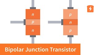
The common emitter configuration is a popular method for utilizing bipolar junction transistors (BJTs) in various applications such as amplification and switching. This configuration provides distinctive input, output, and transfer characteristics that are crucial for electronic circuit design.
Input Characteristics
The input characteristics describe the relationship between the input current, specifically the base current (I_B), and the base-emitter voltage (V_BE). The input curve typically shows how a small change in V_BE leads to a significant influence on I_B, highlighting the transistor's ability to amplify signals.
Output Characteristics
The output characteristics illustrate the collector current (I_C) against the collector-emitter voltage (V_CE) under constant base current conditions. In this region, increasing V_CE leads to a corresponding increase in I_C until saturation, where the transistor becomes fully ON.
Transfer Characteristics
The transfer characteristics curve links I_C to I_B and showcases the transistor's current gain (β), a pivotal factor in amplification. The high β value implies that small input currents can control larger output currents, facilitating signal amplification effectively.
Understanding these characteristics is essential for correctly applying BJTs in circuits and maximizing their functionality based on specific requirements.
Youtube Videos


Audio Book
Dive deep into the subject with an immersive audiobook experience.
Input Characteristics
Chapter 1 of 3
🔒 Unlock Audio Chapter
Sign up and enroll to access the full audio experience
Chapter Content
● Input Characteristics: IBI_B vs. VBEV_{BE}
Detailed Explanation
Input characteristics refer to the relationship between the base current (IB) of the transistor and the base-emitter voltage (VBE). When we plot this relationship on a graph, we can see how changes in VBE affect IB. This characteristic is critical because it helps us understand how the transistor behaves during the input phase and highlights the threshold voltage that must be exceeded for the transistor to turn on.
Examples & Analogies
Imagine trying to open a door (the transistor) with a specific amount of force (VBE) applied to the knob (IB). If you don’t push hard enough (less than the threshold voltage), the door won’t budge. But as soon as you exceed that point, the door swings open (the transistor turns on), allowing for more interactions on the other side.
Output Characteristics
Chapter 2 of 3
🔒 Unlock Audio Chapter
Sign up and enroll to access the full audio experience
Chapter Content
● Output Characteristics: ICI_C vs. VCEV_{CE} for constant IBI_B
Detailed Explanation
Output characteristics describe how the collector current (IC) varies with respect to the collector-emitter voltage (VCE) when the base current is held constant. This relationship shows the operational efficiency of the transistor when used as an amplifier and gives insights into its saturation and cutoff regions. The graphical representation helps visualize how much output current can be expected for different voltage levels.
Examples & Analogies
Think of a water hose connected to a water tap. The tap (VCE) controls how much water (IC) flows through the hose. If the tap is barely open (low VCE), only a small trickle of water comes out. However, as you turn it more (increase VCE), more water flows through until you have maximum flow (saturation).
Transfer Characteristics
Chapter 3 of 3
🔒 Unlock Audio Chapter
Sign up and enroll to access the full audio experience
Chapter Content
● Transfer Characteristics: ICI_C vs. IBI_B
Detailed Explanation
Transfer characteristics illustrate the relationship between the collector current (IC) and the base current (IB). This relationship is crucial for understanding the gain of the transistor, which is often expressed as the current gain (β). A graph of this relationship allows engineers to analyze how effective the transistor is at amplifying the base current into a larger collector current.
Examples & Analogies
Picture a basketball player (IB) who can assist their team in scoring points (IC). The teamwork (the relationship) makes it clear how many more points can be scored due to the player's efforts. If the player puts in a little effort, the points scored may be few, but significant effort can lead to a much larger score increase, reflecting the amplification nature of the transistor.
Key Concepts
-
Common Emitter Configuration: A popular BJT arrangement used for amplification.
-
Input Characteristics: The I_B vs. V_BE relationship that indicates how input influences base current.
-
Output Characteristics: The I_C vs. V_CE relationship showing how collector current behaves with changes in voltage.
-
Transfer Characteristics: Relates I_C and I_B, highlighting the current gain of the transistor.
Examples & Applications
In a common emitter amplifier, a small base current of 10 µA can control a collector current of 1 mA, illustrating the amplification effect.
When biasing a BJT in the common emitter configuration, the input can be set using a potentiometer to adjust V_BE for desired amplification.
Memory Aids
Interactive tools to help you remember key concepts
Rhymes
In a CE, I_B and V_BE, a big rise we see, it’s clear as can be!
Stories
Imagine a gardener (I_B) who carefully waters a plant (V_BE). The more water he gives, the bigger the plant grows (I_C). When he turns on the hose too much (saturation), the plant can't take any more!
Memory Tools
I_B Plots Up (Input Characteristics) - Just remember 'Up' indicates the voltage's growth with respect to base current.
Acronyms
CET - Collector-Emitter-Traits, for the Output Characteristics.
Flash Cards
Glossary
- Common Emitter Configuration
A transistor configuration where the emitter is common to both the input and output circuits, widely used for amplification.
- Input Characteristics
The graphical representation of the relationship between base current and base-emitter voltage.
- Output Characteristics
The graphical representation of the relationship between collector current and collector-emitter voltage.
- Transfer Characteristics
The graph showing the relation between collector current and base current.
Reference links
Supplementary resources to enhance your learning experience.