
Overview of Bipolar Junction Transistors (BJTs)
Enroll to start learning
You’ve not yet enrolled in this course. Please enroll for free to listen to audio lessons, classroom podcasts and take practice test.
Interactive Audio Lesson
Listen to a student-teacher conversation explaining the topic in a relatable way.
What is a BJT?
🔒 Unlock Audio Lesson
Sign up and enroll to listen to this audio lesson

Good morning, class! Today we are discussing Bipolar Junction Transistors or BJTs. Can anyone tell me what a BJT is?

Isn't it a type of transistor that uses both electrons and holes?
Exactly! A BJT is a current-controlled, bipolar device that uses both charge carriers. What do we use BJTs for in circuits?

Amplifying signals and switching in digital circuits?
Correct! It acts as both an amplifier and a switch, crucial for many electronic applications. Let's remember: 'BJTs Bring Joyous Transistor functions!'
Types of BJTs
🔒 Unlock Audio Lesson
Sign up and enroll to listen to this audio lesson

Now, let’s talk about the types of BJTs. Can anyone name them?

There's NPN and PNP!
Great! In an NPN transistor, electrons are the majority carriers, while in a PNP, holes take that role. What flow direction do these two types have?

For NPN, the current flows from collector to emitter, and for PNP, it flows from emitter to collector.
Perfect! Remember, NPN is 'Negative Positive Negative' which is how you can recall the order of the carriers.
Working Principle and Current Relationships
🔒 Unlock Audio Lesson
Sign up and enroll to listen to this audio lesson
Let’s delve into how a BJT works. Who can explain the principles behind its operation?
It has two p-n junctions. The emitter-base junction is forward-biased and the collector-base junction is reverse-biased.
Good job! This configuration allows a small base current to control a larger collector current. Can anyone tell me the current relationships in a BJT?
IE equals IC plus IB, and β equals IC over IB?
Exactly! And α is IC over IE. Let’s use the acronym 'IBA' for currents to remember: 'Input Base Amplifier'.
Modes of Operation
🔒 Unlock Audio Lesson
Sign up and enroll to listen to this audio lesson
BJTs can operate in different modes. Can someone summarize these modes?
Active, Cut-off, and Saturation!
Correct! The Active mode is for amplification, Cut-off is OFF, and Saturation is ON. Who can give me an example of each mode?
In active mode, it's used in amplifiers, cut-off for switching off devices, and saturation for fully turning on a switch!
Well done! Remember this progression: 'A C S' for Active, Cut-off, and Saturation.
BJT Configurations
🔒 Unlock Audio Lesson
Sign up and enroll to listen to this audio lesson
Let’s move on to the configurations of BJTs. What are the three main configurations?
Common Base, Common Emitter, and Common Collector?
Exactly! The Common Emitter is the most popular, providing high voltage and current gain. Can anyone explain the difference in output impedance?
Common Base has low input impedance, Common Collector has high input impedance, and Common Emitter has moderate input.
Good! We can remember this with 'I-M-H' for Input - Moderate to High. Summary: Common configurations define performance!
Introduction & Overview
Read summaries of the section's main ideas at different levels of detail.
Quick Overview
Standard
This section details the characteristics and functioning of Bipolar Junction Transistors (BJTs) as essential components in electronic circuits. It covers their types (NPN and PNP), working principle, current relationships, operational modes, configurations, advantages, disadvantages, and applications. Moreover, it compares BJTs with MOSFETs to highlight their distinct roles in analog and digital circuits.
Detailed
Overview of Bipolar Junction Transistors (BJTs)
Bipolar Junction Transistors (BJTs) are essential semiconductor devices utilized primarily for amplification and switching purposes in electronic circuits. They utilize both electrons and holes as charge carriers and consist of three terminals: Emitter (E), Base (B), and Collector (C). The section categorizes BJTs into NPN and PNP types, detailing their differences in operational characteristics.
The working principle of BJTs illustrates how varying the base current controls a larger collector current. They operate in three modes: Active (for amplification), Cut-off (OFF state), and Saturation (fully ON). Additionally, the section explains different BJT configurations, including Common Base, Common Emitter, and Common Collector, along with their unique impedance and gain characteristics.
BJTs serve various applications such as analog amplification, digital switching, and are compared against MOSFETs, highlighting their differing advantages and limitations. Despite the growing use of MOSFETs in digital circuits, BJTs remain a relevant technology in audio and radio applications. In conclusion, BJTs' high gain and versatility make them valuable in numerous electronic designs.
Youtube Videos


Audio Book
Dive deep into the subject with an immersive audiobook experience.
Definition of a BJT
Chapter 1 of 13
🔒 Unlock Audio Chapter
Sign up and enroll to access the full audio experience
Chapter Content
A Bipolar Junction Transistor (BJT) is a current-controlled, bipolar device that uses both electrons and holes as charge carriers.
It is primarily used for:
● Amplification of analog signals
● Switching in digital logic circuits
Detailed Explanation
A Bipolar Junction Transistor, or BJT, is a type of electronic device that can control current. It is described as a 'bipolar' device because it uses two types of charge carriers: electrons (negatively charged) and holes (positively charged). This unique feature distinguishes it from other types of transistors that might only use one type of carrier.
BJTs serve mainly two purposes: amplification and switching. Amplification refers to the ability of the BJT to take a small input current and increase it to a larger output current, which is valuable in audio and radio signals. Switching refers to the ability to turn on and off digital signals, which is crucial in logic circuits and computers.
Examples & Analogies
Think of a BJT like a water faucet. When you turn the faucet on slightly (small input current), a larger flow of water (output current) comes out. Similar to how you might control the flow of water by adjusting the faucet, a BJT controls electrical current, allowing it to amplify signals or switch circuits on and off.
Three Terminals of a BJT
Chapter 2 of 13
🔒 Unlock Audio Chapter
Sign up and enroll to access the full audio experience
Chapter Content
BJTs have three terminals:
● Emitter (E) – Heavily doped
● Base (B) – Very thin and lightly doped
● Collector (C) – Moderately doped and larger in size
Detailed Explanation
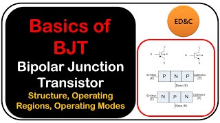
A BJT has three main parts:
1. Emitter (E): This terminal is heavily doped with impurities, which increases the number of charge carriers available. Its job is to send out electrons or holes (depending on the type of transistor).
2. Base (B): This is a very thin and lightly doped section that controls the flow between the emitter and collector. Due to its thin structure, it allows most charge carriers from the emitter to pass on to the collector.
3. Collector (C): This terminal is moderately doped and physically larger. It collects the charge carriers that have moved through the base from the emitter. The size and doping level allow it to handle the maximum current from the circuit.
Examples & Analogies
You can imagine the BJT terminals as different parts of a highway interchange. The emitter is like the entrance ramp that has a lot of cars coming in, the base is the narrow highway that limits how many cars can pass, and the collector is the exit ramp where the cars flow into a larger area. Just as traffic can be controlled at each stage, the flow of electrical current can be managed by the different terminals of the BJT.
Types of BJTs
Chapter 3 of 13
🔒 Unlock Audio Chapter
Sign up and enroll to access the full audio experience
Chapter Content
- NPN Transistor
- PNP Transistor
NPN Transistor PNP Transistor
Electron is majority carrier Hole is majority carrier
Current flows from collector to emitter Current flows from emitter to collector
Positive base-emitter voltage required Negative base-emitter voltage required
Detailed Explanation
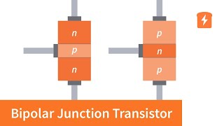
There are two primary types of BJTs: NPN and PNP, each with distinct characteristics:
- NPN Transistor: In this type, electrons are the majority carriers. The current flows from the collector terminal to the emitter. To operate, a positive voltage must be applied to the base-emitter junction.
- PNP Transistor: Here, holes are the majority carriers. The current flows in the opposite direction, from the emitter to the collector. This type requires a negative voltage at the base-emitter junction relative to the emitter to function effectively.
Examples & Analogies
If we think of the NPN and PNP transistors as types of water pumps, the NPN would be a pump that draws water in with a positive push from the control switch, allowing water to flow out. Conversely, the PNP pump would push water out with a negative force, ensuring that the correct direction of flow is maintained, based on its operational voltage.
Working Principle of BJTs
Chapter 4 of 13
🔒 Unlock Audio Chapter
Sign up and enroll to access the full audio experience
Chapter Content
BJT is a sandwich of two p-n junctions, forming two back-to-back diodes:
● Emitter-Base Junction: Forward biased
● Collector-Base Junction: Reverse biased
In an NPN transistor, when the base-emitter junction is forward biased:
● Electrons are injected from emitter to base.
● Since the base is very thin, most electrons diffuse into the collector.
● A small base current IBI_B controls a much larger collector current ICI_C.
Detailed Explanation
The BJT operates based on two p-n junctions that act like two diodes stacked back-to-back. Specifically:
1. Emitter-Base Junction: When the voltage is applied in the correct direction (forward biased), it allows current (electrons) to flow from the emitter into the base.
2. Collector-Base Junction: In contrast, this junction is set up with a reverse bias, which means it opposes the flow of current. This arrangement creates a scenario in which, when electrons flow into the base, they predominantly continue on into the collector.
3. The efficiency of this process is key: a small input current at the base can control a much larger current flowing from collector to emitter. Hence, a small signal can effectively control a larger signal.
Examples & Analogies
Think of the working principle of a BJT like a small lever that controls a large gate. The base current is like a little push on the lever, which then opens up a massive gate allowing a much larger flow of people (current) through. Just a small effort causes a big effect, illustrating how BJTs amplify currents.
Current Relationships in BJT
Chapter 5 of 13
🔒 Unlock Audio Chapter
Sign up and enroll to access the full audio experience
Chapter Content
IE=IC+IB
IB = I_C + I_B
β=IC/IB (current gain)
α=IC/IE (common base current gain)
● β typically ranges from 20 to 200
● α≈0.95 to 0.99
Detailed Explanation
In a BJT, there are relationships that describe how the currents behave:
- IE (Emitter Current) is the sum of the Collector Current (IC) and Base Current (IB). This shows that whatever current comes into the emitter is divided between the collector and base.
- β (Beta) represents current gain and is calculated as the ratio of collector current (IC) to base current (IB). Typically, this value ranges from 20 to 200, indicating how effectively the BJT can amplify the current.
- α (Alpha) is the ratio of collector current to emitter current and is usually close to 1, showing the efficiency of conversion between these currents.
This mathematical understanding enables engineers to predict how effectively a BJT will operate under various conditions.
Examples & Analogies
Imagine watering plants with a watering can. The total amount of water you pour (Emitter Current) is split between two plants—one gets a little water (Base Current), while the other gets the larger share (Collector Current). The ratio of water used for the larger plant compared to the overall volume is like the current gain (β). A more efficient watering can that helps plants grow better is like a BJT with a higher β, demonstrating its amplification capabilities.
Modes of Operation
Chapter 6 of 13
🔒 Unlock Audio Chapter
Sign up and enroll to access the full audio experience
Chapter Content
Region Emitter-Base Collector-Base Description
Active Forward Reverse Amplifier mode
Cut-off Reverse Reverse Transistor is OFF
Saturation Forward Forward Transistor is fully ON (switch)
Inverse Active Reverse Forward Not used in practice
Detailed Explanation
BJTs can operate in different modes based on their biasing conditions:
- Active Mode: Here, the emitter-base junction is forward biased, while the collector-base junction is reverse biased. This allows the transistor to amplify signals effectively.
- Cut-off Mode: In this state, both junctions are reverse biased, meaning no current flows through the transistor. The BJT is effectively OFF.
- Saturation Mode: Both the emitter-base and collector-base junctions are forward biased. This means the transistor is fully ON, allowing maximum current flow, functioning as a switch.
- Inverse Active Mode: Less commonly used, where the roles of the terminals are reversed. It is not typically applied in practical circuits due to inefficiencies.
Examples & Analogies
Think of a BJT like a traffic light system. In active mode, traffic is flowing smoothly controlled by the lights, like a signal being amplified. In cut-off mode, the lights are red, and vehicles must stop, representing no current flow. Saturation mode is like a green light where traffic can move freely, as the gate is wide open for current to pass. The inverse active mode is rare, similar to a malfunctioning light where vehicles are not directed correctly.
BJT Configurations
Chapter 7 of 13
🔒 Unlock Audio Chapter
Sign up and enroll to access the full audio experience
Chapter Content
- Common Base (CB)
○ Low input impedance, high output impedance
○ Voltage gain: High
○ No phase shift - Common Emitter (CE)
○ Moderate input/output impedance
○ Voltage & current gain: High
○ 180° phase shift between input & output - Common Collector (CC) (Emitter Follower)
○ High input, low output impedance
○ Voltage gain < 1
○ No phase shift (used for buffering)
Detailed Explanation
BJTs can be configured in three main ways:
1. Common Base Configuration: This setup has low input impedance and high output impedance, offering high voltage gain without changing the phase of the input signal. It's useful when low input current is needed.
2. Common Emitter Configuration: This is the most popular configuration. It has moderate input and output impedances, delivers high voltage and current gains, but introduces a 180-degree phase shift meaning the output signal is inverted compared to the input.
3. Common Collector Configuration (also known as Emitter Follower): Typically features high input impedance and low output impedance with a gain that is less than one. It provides no phase shift and is used for buffering, ensuring that the output doesn't affect the input signal.
Examples & Analogies
Imagine different styles of public speaking venues. Common Base is like addressing a small audience (high gain but low input), ideal for close discussions. Common Emitter is akin to giving a large speech where the message is strong, but the attention may be inverted (180-degree phase shift). Common Collector is like a counseling session where you listen carefully (high input) but provide reassurance without altering the main intention of the message (buffering).
BJT as a Switch
Chapter 8 of 13
🔒 Unlock Audio Chapter
Sign up and enroll to access the full audio experience
Chapter Content
● Cut-off Region → OFF State
● Saturation Region → ON State
● Used in digital logic, microcontroller interfaces, and relay drivers
Detailed Explanation
BJTs can operate as switches, functioning effectively based on their modes:
- In the Cut-off Region, the BJT is in the OFF state, meaning no current flows through it. It acts like an open switch.
- In the Saturation Region, the BJT is fully ON, allowing current to flow freely. It mimics a closed switch. This switching ability makes BJTs suitable for various applications, such as digital logic circuits, where they can control signals on and off, and microcontrollers that interface with other components.
Examples & Analogies
You can think of a BJT as a light switch in your classroom. When the switch is down (cut-off), the light is OFF (no current flow). When you push it up (saturation), the light turns ON (current flows through). Just as you control the classroom lights, BJTs control the electrical current in circuits, allowing you to turn devices on and off.
BJT as an Amplifier
Chapter 9 of 13
🔒 Unlock Audio Chapter
Sign up and enroll to access the full audio experience
Chapter Content
Operates in Active Region.
The small base current controls a large collector current, making it suitable for signal amplification in:
● Audio amplifiers
● RF amplifiers
● Sensor signal conditioning
Detailed Explanation
BJTs are highly effective as amplifiers when they operate in the Active Region. In this state, a small current at the base can significantly control a larger current through the collector. This characteristic is especially beneficial in applications like audio amplifiers (enhancing sound quality), RF amplifiers (boosting radio signals), and sensor signal conditioning (making weak sensor signals usable).
Examples & Analogies
Imagine a small microphone that captures your voice and is connected to a powerful speaker. The microphone's small electrical signal (base current) gets amplified by the speaker system (collector current), allowing your voice to fill a large room. This same principle applies to BJTs, which take a small signal and amplify it for broader applications.
Advantages and Disadvantages of BJTs
Chapter 10 of 13
🔒 Unlock Audio Chapter
Sign up and enroll to access the full audio experience
Chapter Content
✅ Advantages:
● High gain-bandwidth product
● Simple biasing
● Good linearity in analog operation
❌ Disadvantages:
● Higher power consumption than MOSFETs
● Lower input impedance
● Thermal runaway risk
Detailed Explanation
BJTs come with both pros and cons:
Advantages:
- High gain-bandwidth product means they can amplify signals very effectively across a wide range.
- Simple biasing makes them easier to set up in circuits compared to some alternatives.
- Good linearity means the output signal closely resembles the input, which is crucial for various analog applications.
Disadvantages:
- BJTs consume more power than MOSFETs, making them less efficient for certain applications.
- They have lower input impedance, which can lead to more power loss in some circuits.
- Thermal runaway risk occurs when increased temperature causes more current flow, leading to even more heat and potentially damaging the transistor.
Examples & Analogies
Think of BJTs like a traditional gasoline car. They can be powerful (high gain) and easy to fuel up (simple biasing), but they consume a lot of gas (power consumption) and can overheat if pushed too hard (thermal runaway). On the other hand, electric cars (like MOSFETs) use less energy and have fewer issues with overheating but may not be as robust in certain performance areas.
BJT vs MOSFET Comparison
Chapter 11 of 13
🔒 Unlock Audio Chapter
Sign up and enroll to access the full audio experience
Chapter Content
Feature BJT MOSFET
Type Bipolar (2 carrier types) Unipolar (1 carrier type)
Control Current-controlled Voltage-controlled
Input Impedance Low Very High
Switching Speed Moderate High
Power Consumption Higher Lower
Preferred Use Analog circuits Digital circuits, ICs
Detailed Explanation
BJTs and MOSFETs are two different types of transistors with unique characteristics:
- Type: BJTs are bipolar, which means they use both electrons and holes. MOSFETs are unipolar and rely on one type of charge carrier, making them generally more efficient.
- Control: BJTs are controlled by current, while MOSFETs are controlled by voltage, leading to differences in their operation.
- Input Impedance: BJTs have low input impedance, which affects their power consumption, whereas MOSFETs have very high input impedance. This trait allows them to use less power.
- Switching Speed: MOSFETs typically switch faster than BJTs, making them better suited for rapid on/off applications.
- Power Consumption: BJTs generally consume more power than MOSFETs, especially under high switching speeds.
- Preferred Use: BJTs are often used in analog circuits, while MOSFETs are more common in digital and integrated circuits.
Examples & Analogies
You might think of BJTs and MOSFETs like two types of gym trainers. A BJT trainer helps you build strength with hands-on guidance (current-controlled), while a MOSFET trainer uses a unique strategy (voltage-controlled) that allows for efficiency and rapid results. Each has its strengths depending on what you're trying to achieve—whether it's building muscle gradually or getting super fast recovery.
Applications of BJTs
Chapter 12 of 13
🔒 Unlock Audio Chapter
Sign up and enroll to access the full audio experience
Chapter Content
● Low-noise amplifiers
● Audio and radio amplifiers
● Digital logic gates (historically TTL)
● Switching regulators
● Relay drivers and LED drivers
Detailed Explanation
BJTs find use in a variety of applications due to their versatile and reliable operating characteristics:
- They are employed as low-noise amplifiers in audio equipment to ensure clear sound reproduction.
- BJTs serve as amplifiers in audio and radio circuits, enhancing weak signals so they can be used effectively.
- Historically, they were pivotal in digital logic gates, particularly in TTL (Transistor-Transistor Logic) circuits.
- BJTs are used in switching regulators to efficiently manage power supply conversion.
- They also control larger loads as relay drivers and help illuminate LEDs in various circuits.
Examples & Analogies
Imagine BJTs as the backbone of a concert. They help amplify the musicians' sound (low-noise amplifiers) to ensure the audience hears everything clearly. They are part of the equipment that connects performers with the audience (switching regulators and relay drivers), just as BJTs connect electrical signals, ensuring everything runs smoothly.
Summary of Key Concepts
Chapter 13 of 13
🔒 Unlock Audio Chapter
Sign up and enroll to access the full audio experience
Chapter Content
● BJT is a current-controlled bipolar device.
● Operates in three regions: active (amplification), cut-off (OFF), saturation (ON).
● Has three configurations: CE (popular), CB, CC.
● Amplifies current with current gain β.
● Still used in analog designs despite dominance of MOSFETs in digital.
Detailed Explanation
In summary, a BJT is a current-controlled device that uses both types of charge carriers (electrons and holes). Its three primary operating regions—active for amplification, cut-off where it is OFF, and saturation where it is fully ON—define its function as a switch or amplifier. The three configurations (Common Emitter, Common Base, and Common Collector) determine how the device is used in different applications, especially with respect to gain and phase shifts. Despite the growing preference for MOSFETs in digital applications, BJTs remain crucial in many analog circuit designs.
Examples & Analogies
You can think of BJTs as a versatile toolbox. Depending on the project (configuration), you can use different tools (active, cut-off, saturation) to achieve your desired result (amplification or switching). Just like traditional tools have their place in the workshop even with newer technology available, BJTs continue to play a vital role in the world of electronics.
Key Concepts
-
BJT: A current-controlled device utilizing both charge carriers for signal amplification and switching.
-
NPN and PNP Transistors: Two categories of BJTs distinguished by majority charge carriers.
-
Active, Cut-off, and Saturation Modes: Different operational states of BJTs that serve specific purposes in circuits.
-
Common Emitter Configuration: The most popular configuration for BJTs, providing high overall gain.
Examples & Applications
NPN transistors are commonly used in amplifiers due to their efficient current gain properties.
BJTs are utilized in digital switches, handling tasks in microcontrollers and LED drivers.
Memory Aids
Interactive tools to help you remember key concepts
Rhymes
To amplify a sound, let BJTs abound; in modes they sway, cutting off and on every day.
Stories
Imagine a busy street (BJT) where the Emitter (E) sends people (electrons) to the Base (B). The Base, acting like a thin bridge, allows many to flow to the Collector (C) where they gather and continue their journey. It’s all about controlling who gets through!
Memory Tools
Remember 'I B A'; Input, Base, Amplify - the key sequence for understanding BJT operation.
Acronyms
NPN - 'Negative Positive Negative' which helps to remember the order of the majority carrier type.
Flash Cards
Glossary
- Bipolar Junction Transistor (BJT)
A transistor that uses both electrons and holes as charge carriers.
- NPN Transistor
A type of BJT where electrons are the majority carriers.
- PNP Transistor
A type of BJT where holes are the majority carriers.
- Emitter
The terminal in a BJT that injects charge carriers into the base.
- Base
The thin central region in a BJT that controls the flow of carriers.
- Collector
The terminal in a BJT that collects charge carriers from the base region.
- Current Gain (β)
The ratio of the collector current (IC) to the base current (IB) in a BJT.
- Active Mode
The mode in which a BJT amplifies signals.
- Cutoff Mode
The mode in which a BJT is turned off.
- Saturation Mode
The mode in which a BJT is fully on, allowing maximum current to pass.
- Common Emitter Configuration
The most widely used BJT configuration, providing high voltage and current gain.
- Input Impedance
The resistance to incoming signals at the input terminal.
Reference links
Supplementary resources to enhance your learning experience.