
Summary of Key Concepts
Enroll to start learning
You’ve not yet enrolled in this course. Please enroll for free to listen to audio lessons, classroom podcasts and take practice test.
Interactive Audio Lesson
Listen to a student-teacher conversation explaining the topic in a relatable way.
Introduction to BJTs
🔒 Unlock Audio Lesson
Sign up and enroll to listen to this audio lesson

Let's start our discussion on Bipolar Junction Transistors, or BJTs. Who can tell me what a BJT is?

Isn't it a type of transistor that can control current?
That's correct! A BJT is indeed a current-controlled bipolar device that uses both electrons and holes as charge carriers. Can anyone tell me the three terminals of a BJT?

Emitter, Base, and Collector?
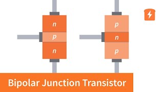
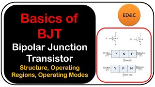
Exactly! The Emitter is heavily doped, the Base is very thin and lightly doped, and the Collector is moderately doped. This configuration allows the BJT to amplify signals efficiently. Let's remember this with the acronym **EBC** for Emitter, Base, and Collector.

EBC, got it!
Great! Now, let's summarize what we discussed: BJTs are current-controlled devices with three terminals, which are crucial for amplification and switching in various circuits.
Operating Regions of BJTs
🔒 Unlock Audio Lesson
Sign up and enroll to listen to this audio lesson

Let's move on to the operating regions of BJTs: active, cut-off, and saturation. Can someone explain what happens in each region?

In the active region, the transistor is used for amplifying signals, right?
Correct! When in the active region, the BJT amplifies the input signal. What about the cut-off region?
The transistor is OFF in cut-off, meaning no current flows.
Excellent! And in the saturation region?
In saturation, it's fully ON, allowing maximum current to flow.
Exactly! Remember this pattern: **Active → Amplify, Cut-off → OFF, Saturation → ON**. Now let's review: BJTs operate in three regions crucial for controlling their function.
BJT Configurations
🔒 Unlock Audio Lesson
Sign up and enroll to listen to this audio lesson
Now let's talk about the configurations of BJTs. What configurations do we have?
Common Emitter, Common Base, and Common Collector?
Correct! The Common Emitter is the most popular configuration due to its high gain and phase reversal properties. Can anyone say what the Common Base configuration is known for?
It has low input impedance and high output impedance?
Exactly! And how about the Common Collector?
That one is like an emitter follower, right? It has high input but low output impedance.
Right again! Remember **CE, CB, CC** stands for Common Emitter, Common Base, and Common Collector, respectively. BJTs remain relevant in analog applications despite advances in digital technology. Great discussion!
Introduction & Overview
Read summaries of the section's main ideas at different levels of detail.
Quick Overview
Standard
The summary covers the essential elements of BJTs as current-controlled bipolar devices functioning in active, cut-off, and saturation regions. It highlights three primary configurations (common emitter, common base, and common collector), their amplification capability reflected in the current gain (β), and their applications, emphasizing their use in analog designs.
Detailed
Summary of Key Concepts
The Bipolar Junction Transistor (BJT) is a current-controlled bipolar device fundamental in electronic circuits. BJTs operate in three main regions: active, used for signal amplification; cut-off, indicating the transistor is OFF; and saturation, where it is fully ON.
BJTs exist primarily in three configurations:
1. Common Emitter (CE) - the most popular, providing high gain and a phase shift.
2. Common Base (CB) - characterized by low input and high output impedance.
3. Common Collector (CC) - also known as the emitter follower, this configuration offers high input and low output impedance with a voltage gain of less than 1.
BJTs are notable for their ability to amplify current, denoted by the current gain β, which measures how much the collector current (I_C) increases with an increase in base current (I_B). Despite the prevailing use of MOSFETs in digital applications, BJTs remain essential in analog circuits due to their high performance in amplification.
Youtube Videos


Audio Book
Dive deep into the subject with an immersive audiobook experience.
Overview of BJT Functionality
Chapter 1 of 5
🔒 Unlock Audio Chapter
Sign up and enroll to access the full audio experience
Chapter Content
● BJT is a current-controlled bipolar device.
Detailed Explanation
A Bipolar Junction Transistor (BJT) is categorized as a current-controlled device because its operation primarily relies on the control of base current to regulate larger currents flowing from the collector to the emitter. The term 'bipolar' implies that the device uses two types of charge carriers: electrons (negative charge carriers) and holes (positive charge carriers).
Examples & Analogies
Think of a BJT like a water faucet. The base current acts like the handle of the faucet; when you turn it to a certain position (open), a larger flow of water (current) comes out of the faucet (from collector to emitter). If the handle is turned off (no base current), the flow of water stops.
Operating Regions of BJTs
Chapter 2 of 5
🔒 Unlock Audio Chapter
Sign up and enroll to access the full audio experience
Chapter Content
● Operates in three regions: active (amplification), cut-off (OFF), saturation (ON).
Detailed Explanation
BJTs can operate in three distinct regions. The 'active' region is where the transistor is used for amplification of signals, meaning it can take a small input current and produce a larger output current. The 'cut-off' region is the OFF state, where no current flows through the transistor. In the 'saturation' region, the transistor is fully ON, allowing maximum current to flow from collector to emitter.
Examples & Analogies
Imagine a light switch. When the switch is in the up position, the light is fully on (saturation). When it's down, the light is off (cut-off). When the switch is halfway, the light might glow faintly as it tries to dim down (active region).
BJT Configurations
Chapter 3 of 5
🔒 Unlock Audio Chapter
Sign up and enroll to access the full audio experience
Chapter Content
● Has three configurations: CE (popular), CB, CC.
Detailed Explanation
Bipolar Junction Transistors can be used in three configurations: Common Emitter (CE), Common Base (CB), and Common Collector (CC). Each configuration has its unique characteristics in terms of input and output impedance, voltage gain, and phase shifts. The Common Emitter configuration is popular for amplification purposes due to its high voltage gain and moderate input/output impedance.
Examples & Analogies
Think of different ways to arrange a string of lights in a display. If you connect the lights in series (Common Emitter), they shine brightly and are easy to control (popular). If you connect them in parallel (Common Collector), they share the same voltage but each is less bright (lower output impedance). Connecting them in unique arrangements leads to different visual effects (varied gains and phase shifts).
Current Gain in BJTs
Chapter 4 of 5
🔒 Unlock Audio Chapter
Sign up and enroll to access the full audio experience
Chapter Content
● Amplifies current with current gain β.
Detailed Explanation
One of the key advantages of BJTs is their ability to amplify current. This is quantified by a parameter called current gain, denoted by β (beta). The current gain indicates how much the output current (collector current) is greater than the input current (base current). For example, if β is 100, then a base current of 1mA can control a collector current of 100mA.
Examples & Analogies
Imagine a small lever that can lift a heavy weight. The base current is the effort you use to push down on the lever (a small force), and the heavy weight being lifted represents the amplified current (a larger force). The lever amplifies your tiny effort into a massive power that can lift the load — much like how a small input current can control a much larger output current in a BJT.
Relevance of BJTs in Modern Applications
Chapter 5 of 5
🔒 Unlock Audio Chapter
Sign up and enroll to access the full audio experience
Chapter Content
● Still used in analog designs despite dominance of MOSFETs in digital.
Detailed Explanation
Despite the rise and popularity of Metal-Oxide-Semiconductor Field-Effect Transistors (MOSFETs) in digital applications, BJTs remain essential in various analog circuits. Their high gain and good linearity make them suitable for audio amplifiers, radio frequency amplifiers, and other applications where precise amplification is required.
Examples & Analogies
Consider how classic vinyl records still have a devoted following despite the prevalence of digital music. Vinyl records (BJTs) offer a unique warmth and character that many audiophiles appreciate, much like how BJTs continue to serve crucial roles in audio equipment, despite the convenience offered by digital formats (MOSFETs).
Key Concepts
-
BJT: A current-controlled bipolar device.
-
Operating Regions: Active, Cut-off, and Saturation.
-
Configurations: Common Emitter, Common Base, and Common Collector.
-
Current Gain (β): Measures amplification capacity.
Examples & Applications
BJTs are widely used in audio amplifiers to enhance sound signals.
In digital circuits, BJTs historically formed the basis of logic gates like TTL.
Memory Aids
Interactive tools to help you remember key concepts
Rhymes
In the BJT's three regions, signals flow and stop, / Active to amplify, in Cut-off it won't hop.
Stories
Imagine BJT as a water pump: in the active region, water flows out powerfully, in cut-off it stops completely, and in saturation, it pours out quickly without holding back.
Memory Tools
Remember AC—Active for amplifying, Cut-off for OFF, and Saturation for maximum flow.
Acronyms
Use the acronym **EBC**
Emitter
Base
Collector to remember the terminals.
Flash Cards
Glossary
- BJT
A Bipolar Junction Transistor, a current-controlled bipolar device.
- Active Region
Operation mode where the BJT amplifies input signals.
- Cutoff Region
Operation mode where the BJT is OFF, with no current flow.
- Saturation Region
Operation mode where the BJT is fully ON, allowing maximum current flow.
- Common Emitter
Configuration providing high voltage and current gain with a 180° phase shift.
- Current Gain (β)
Ratio of the collector current to the base current in a transistor.
Reference links
Supplementary resources to enhance your learning experience.