
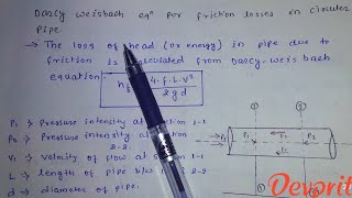
Application of the Darcy Weisbach Equation
Enroll to start learning
You’ve not yet enrolled in this course. Please enroll for free to listen to audio lessons, classroom podcasts and take practice test.
Interactive Audio Lesson
Listen to a student-teacher conversation explaining the topic in a relatable way.
Understanding Local Loss Coefficients
🔒 Unlock Audio Lesson
Sign up and enroll to listen to this audio lesson

Today, we'll discuss how local loss coefficients affect head loss in pipe systems. Can anyone tell me what loss coefficients are?

Are those the values for entry and exit points of the pipe?
Exactly! We typically consider an entry loss coefficient of 0.5 and an exit of 1. This helps us to quantify how much energy is lost at these points.

Why do we need to account for these losses?
Great question! These losses impact the overall system efficiency. We want to ensure that our pumps can compensate for these head losses!
Remember: 'Entry is 0.5, Exit is 1' — think E=0.5, X=1 as our memory aid.

So if we have a longer pipe, does that mean greater losses?
Yes! The longer the pipe, the higher the major losses due to friction. Let's summarize: We've covered loss coefficients and their importance in calculating head loss.
Calculating Head Loss Using the Darcy Weisbach Equation
🔒 Unlock Audio Lesson
Sign up and enroll to listen to this audio lesson

Now, let's dive into the Darcy Weisbach equation itself. Can anyone recall the major components of this equation?

Isn't it something like head loss equals friction factor times length divided by diameter?
"Close! It actually is:
Examples of Calculating Energy Loss
🔒 Unlock Audio Lesson
Sign up and enroll to listen to this audio lesson
We'll now look at a specific example problem involving a pipe. Suppose we have a friction factor of 0.04, length of 2000m, and diameter of 0.2m. What is our total head loss?
Doesn't the equation take all those variables into account?
Exactly! By substituting these values into our Darcy Weisbach equation, we can find head loss. Go ahead and calculate it!
"So that gives us 8m total head loss!
Introduction & Overview
Read summaries of the section's main ideas at different levels of detail.
Quick Overview
Standard
The Darcy Weisbach equation is instrumental in analyzing fluid flow in pipes, as it quantifies energy losses associated with friction and other minor losses. Key parameters such as friction factor, pipe length, and loss coefficients are discussed along with practical examples.
Detailed
Application of the Darcy Weisbach Equation
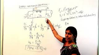
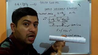
The Darcy Weisbach equation is an essential tool used in fluid dynamics to determine the head loss due to friction in piping systems. When fluid flows through a pipe, energy is lost primarily due to friction between the fluid and the pipe walls. This section summarizes how to apply the Darcy Weisbach equation effectively, calculating both major and minor losses.
Key Parameters
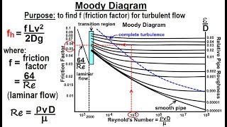
- Friction Factor (f): A dimensionless number that represents the friction in the pipe, influenced by the flow regime (laminar or turbulent) and pipe roughness.
- Pipe Length (L): The distance the fluid travels within the pipe, measured in meters.
- Pipe Diameter (D): The internal diameter of the pipe, crucial for calculating flow velocity and Reynolds number.
- Total Head Loss (hL): The energy loss from the fluid flow, measured in meters, reflecting the overall efficiency of the system.
Loss Coefficients
Loss coefficients at different points are crucial to accurately compute total head loss. At the pipe entry, a loss coefficient of 0.5 is considered, while the exit typically has a coefficient of 1, assuming negligible loss.
Example Problems
The section illustrates the application of the Darcy Weisbach equation through several examples, demonstrating how to substitute values into the equation to derive essential characteristics such as flow velocity and required energy input for pumps.
Significance
Understanding the application of the Darcy Weisbach equation is fundamental for engineers and scientists when designing efficient piping systems and ensures that they can account for energy losses effectively.
Youtube Videos


Audio Book
Dive deep into the subject with an immersive audiobook experience.
Friction Factors and Head Loss Coefficient
Chapter 1 of 5
🔒 Unlock Audio Chapter
Sign up and enroll to access the full audio experience
Chapter Content
So the friction factors data what is given it length of the pipe the diameters and total head losses. The loss coefficient in terms of velocity head as you know it at the exit we consider as 1, at the entry we consider 0.5.
Detailed Explanation
In fluid dynamics, the friction factor is a measure of the resistance to flow in a pipe due to the friction between the fluid and the pipe walls. In this section, we're discussing how to assess the total head loss in a pipe system, particularly looking at the entry loss and exit loss. For entry, we use a loss coefficient of 0.5, which accounts for friction as the flow enters the pipe, slowing down the fluid slightly. At the exit, we consider a loss coefficient of 1, indicating the full impact of velocity head loss when the fluid exits the pipe. Understanding these coefficients is crucial for calculating energy losses in pipe flows.
Examples & Analogies
You can think of the entry loss like a car entering a garage. When the car enters (fluid enters the pipe), it slows down due to the smaller entrance. The exit loss is like the car exiting; it may have some drag or resistance as it leaves, thus experiencing a change in speed. The calculation helps us predict how much energy will be wasted overcoming this friction.
Applying the Darcy Weisbach Equation
Chapter 2 of 5
🔒 Unlock Audio Chapter
Sign up and enroll to access the full audio experience
Chapter Content
Now we apply the Darcy Weisbach equations to compute the energy losses for the major losses or the pipe flow because of the frictions components and the minor losses.
Detailed Explanation
The Darcy Weisbach equation is a fundamental formula for calculating head loss due to friction in a pipe. The equation incorporates both friction factors and velocity head to determine the total energy loss in the system. The equation is critical in engineering applications, especially for designing piping systems. It helps engineers estimate how much pressure is lost due to friction and how much additional pressure (or pumping power) is needed to maintain the desired flow rate.
Examples & Analogies
Imagine water flowing through a hose to water your garden. If the hose is long and has many twists and turns, you will need a stronger pump to ensure the water reaches the end, as some energy is lost due to friction. The Darcy Weisbach equation helps quantify how much of that pressure is lost, enabling you to choose the right pump.
Solving for Velocity and Head Loss
Chapter 3 of 5
🔒 Unlock Audio Chapter
Sign up and enroll to access the full audio experience
Chapter Content
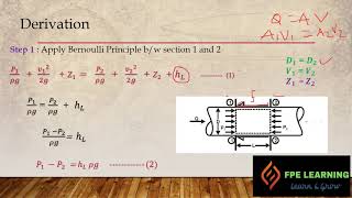
By substituting these and we can get a series of equations and upon solving we will get the velocity.
Detailed Explanation
After establishing the head loss through the Darcy Weisbach equation, values for friction factors, lengths, diameters, and coefficients need to be substituted into the equation. This will lead to a set of equations that can be solved, usually resulting in a quadratic equation, from which the fluid velocity can be determined. Knowing the velocity is critical for understanding flow rates and optimizing systems for energy efficiency and effectiveness.
Examples & Analogies
Think of baking a cake where you have to mix all the ingredients correctly to get the desired texture. Similarly, you mix the values in the Darcy Weisbach equation to determine the right flow velocity in your system. Just as the right cake batter leads to a perfect cake, the correct velocity leads to efficient flow.
Example Calculations
Chapter 4 of 5
🔒 Unlock Audio Chapter
Sign up and enroll to access the full audio experience
Chapter Content
If I put the energy losses V1, V2 = 0, and solving this pumping head, okay which will give it the elevation difference and the major and minor losses component.
Detailed Explanation
This section introduces a practical example where the values for velocities at two points are set to zero, simplifying the problem to focus on the energy losses due to elevation changes and other frictional losses in the system. This method of solving showcases how professionals approach real-world problems by simplifying equations, which helps in finding the necessary pumping head or energy required to transport the fluid effectively.
Examples & Analogies
Like lifting a bucket of water from a well, if you consider the height of the well and the friction of the rope, knowing exactly how much you need to pull (pumping head) is crucial. This approach helps determine how much effort is needed in various scenarios.
Conclusion and Summation
Chapter 5 of 5
🔒 Unlock Audio Chapter
Sign up and enroll to access the full audio experience
Chapter Content
With this way, we generally use a design problem to solve the problem, do the designing of the piping system, additional energy like a pumping or in hydropower projects.
Detailed Explanation
At the conclusion of this section, the discussion pivoted to how the concepts learned apply broadly in design problems in various engineering fields, particularly in piping systems and hydropower projects. The emphasis is on using the learned equations and principles to put together whole systems that efficiently transport fluids. Understanding these parameters leads to better design practices and energy-efficient solutions.
Examples & Analogies
Think of designing a theme park water ride. You need to ensure that water flows smoothly from start to finish, accounting for every twist and turn, and the energy required to keep the flow moving. Just as engineers use these equations to ensure water rides operate efficiently, they use these principles for all fluid transport systems.
Key Concepts
-
Friction Factor: A number that quantifies the friction loss in a pipe.
-
Head Loss: Energy that is lost as the fluid travels through the pipe.
-
Loss Coefficients: Values used to account for energy losses at bends, valves, and pipe entrances/exits.
-
Reynolds Number: A dimensionless value that helps predict flow behavior as laminar or turbulent.
Examples & Applications
A pipe with a length of 2000m, a diameter of 0.2m, and a friction factor of 0.04 has a total head loss of 8m.
In a dual-reservoir system, calculating energy loss includes entry/exit coefficients and various minor losses from bends and valves.
Memory Aids
Interactive tools to help you remember key concepts
Rhymes
Friction flows, but not too slow, for 0.5 at the start is how we go!
Stories
Imagine a water slide; the entry is gentle (0.5), while the exit is like a swift splash down (1). Energy loss is like the slide's height – keep track of it!
Memory Tools
For entry and exit losses, remember 'E for Entry (0.5), E for Easy', then 'X for Exit (1), finish line is in!'
Acronyms
H.L.E.D (Head Loss Energy Drop)
The method to recall head losses - Head
Loss
Entry
Drop!
Flash Cards
Glossary
- Darcy Weisbach Equation
A formula used to calculate head loss due to friction in a pipe, factoring in the pipe's length, diameter, and flow characteristics.
- Friction Factor
A coefficient that represents the resistance to flow due to friction in the pipe.
- Total Head Loss
The total energy loss experienced by fluid as it flows through the pipe, usually expressed in meters.
- Loss Coefficient
A dimensionless number representing the head loss due to fittings, bends, or changes in cross-section.
- Reynolds Number
A dimensionless number that describes the flow regime, indicating whether the flow is laminar or turbulent.
Reference links
Supplementary resources to enhance your learning experience.