
Description of the Design Problem
Enroll to start learning
You’ve not yet enrolled in this course. Please enroll for free to listen to audio lessons, classroom podcasts and take practice test.
Interactive Audio Lesson
Listen to a student-teacher conversation explaining the topic in a relatable way.
Understanding Friction and Head Loss in Pipes
🔒 Unlock Audio Lesson
Sign up and enroll to listen to this audio lesson

Today, we're starting with friction factors. Who can tell me what a friction factor is in relation to pipe flow?

Is it how much energy is lost due to the friction in the pipe?
Exactly! The friction factor quantifies the frictional energy loss in the flow. In our example, it's given as 0.04. Let's remember that a lower friction factor means less energy loss! This can be thought of as being more 'sneaky' with the water flow.

How does the length of the pipe affect this?
Good question! Longer pipes generally lead to more friction and, therefore, greater total head loss. In our scenario, we have a pipe that is 2000 m long. So, can anyone tell me why we need to calculate head loss?

We calculate it to determine the energy needed to maintain flow through the pipe.
Exactly! And knowing this helps in designing appropriate pumping systems. Let's summarize: Friction factors are critical for understanding energy losses, and longer pipes increase these losses!
Darcy-Weisbach Equation
🔒 Unlock Audio Lesson
Sign up and enroll to listen to this audio lesson

Now let's apply the **Darcy-Weisbach equation**. Who remembers what this equation helps us find?

It helps us calculate the head loss due to friction.
Correct! The equation is represented as head loss equals friction factor multiplied by length, multiplied by the velocity squared, divided by appropriate constants. Let's calculate the head loss given our friction factor and pipe details. What do we substitute into the equation?
We'll use the friction factor of 0.04, length of 2000 m, and the diameter of 0.2 m.
Right! And we also consider the loss coefficients for entry and exit in our calculations. Why do you think we need these?
To account for additional energy losses at the transitions of the pipe?
Exactly! Entry and exit losses can significantly affect the total head loss. Let’s summarize: The **Darcy-Weisbach equation** is essential for quantifying energy losses in pipe flow!
Calculating Pump Horsepower Requirements
🔒 Unlock Audio Lesson
Sign up and enroll to listen to this audio lesson
Let's discuss how to determine the horsepower needed for our pumping systems. Why is this important?
To ensure our pump can overcome the energy losses we've calculated.
Exactly! Now, we have a setup where we want to lift water up to a difference of 30 m. We also factor in the total head loss from earlier calculations. Can anyone help calculate this?
Do we need the head loss to find the pump head requirement?
Correct! If we add the elevation difference to the total head loss, we can find the total pump head needed. In our case, that comes to 57 m. Next, how do we translate that into horsepower?
By multiplying the required head by the flow properties and dividing it by the conversion factor for horsepower.
Exactly right! So we can summarize that calculating pump horsepower is crucial for ensuring our system can handle energy losses effectively!
Practical Application of Loss Coefficients
🔒 Unlock Audio Lesson
Sign up and enroll to listen to this audio lesson
Now we're moving to minor losses due to fittings in our pipe system. Can anyone list some of the factors we need to consider?
Bends, elbows, and valves!
Exactly! Each of these has a specific loss coefficient, which is essential for calculating energy losses accurately. For example, a regular elbow can be 0.95 while a half-open valve can be 2.7. How do these coefficients affect our calculations?
They increase the overall energy losses, making it essential for our designs to accommodate for them!
Very well put! We have to be vigilant about calculating these minor losses alongside the major losses. Can anyone think of how this impacts our total system performance?
It can lead to inefficient systems if not properly accounted for, which can increase operational costs.
Great insight! So let's summarize: Understanding minor losses is just as important as major losses for effective design!
Introduction & Overview
Read summaries of the section's main ideas at different levels of detail.
Quick Overview
Standard
The section focuses on quantifying friction and head losses in pipe flow, utilizing the Darcy-Weisbach equation. It discusses specific parameters like friction factors, loss coefficients for entry and exit, and how to determine pump requirements in various scenarios, emphasizing the importance of understanding these losses for effective pipeline design.
Detailed
Description of the Design Problem
In this section, we delve into crucial aspects of fluid mechanics related to pipe flow, focusing particularly on how to calculate energy losses approximated by the Darcy-Weisbach equation. The text outlines fundamental parameters such as:
- Friction Factor: Given as 0.04, this factor plays a pivotal role in determining how much energy is lost due to friction along the pipe's length.
- Pipe Length: Defined at 2000 m, it impacts the total head loss that occurs over the entire flow distance.
- Diameter: At 0.2 m, size significantly influences flow characteristics and energy loss.
- Total Head Loss: Stated as 8 m, it indicates the total energy loss in the system.
Key coefficients are established as follows:
- Loss Coefficient for Entry: Assumed to be 0.5, indicating some loss as fluid enters the pipe.
- Loss Coefficient for Exit: Taken as 1, indicating ideally no loss at the exit aside from what is already calculated.
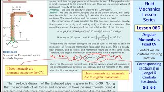
The Darcy-Weisbach equation is employed to ascertain the energy losses due to friction and various minor losses introduced by fittings such as bends, valves, and entry/exit points. These calculations require an understanding of the flow characteristics, including determining the Reynolds number and employing Moody’s chart for friction factors based on flow regimes. Finally, we discuss practical applications in scenarios with multiple connections (e.g., reservoirs) and how to compute necessary pump horsepower to overcome energy losses and achieve the desired flow rates.
The mastering of these calculations and principles is essential for engineers and designers tasked with creating efficient fluid transport systems.
Youtube Videos


Audio Book
Dive deep into the subject with an immersive audiobook experience.
Understanding the Friction Factors
Chapter 1 of 4
🔒 Unlock Audio Chapter
Sign up and enroll to access the full audio experience
Chapter Content
The friction factors data includes the length of the pipe, diameters, and total head losses. The loss coefficient in terms of velocity head at the exit is considered as 1, and at the entry, it is considered as 0.5.
Detailed Explanation
In fluid mechanics, when analyzing the flow of fluid through pipes, it's crucial to consider friction factors. These factors are influenced by the length of the pipe, its diameter, and the loss of energy (head losses) that occurs as fluid moves through the pipe. The velocity head loss is a representation of how velocity affects energy loss at different points in the system. At the entry point of the pipe, we assign a loss coefficient of 0.5, which reflects an initial energy loss as the fluid enters. Meanwhile, at the exit, the coefficient is set to 1, indicating that the flow is more stable when leaving the pipe.
Examples & Analogies
Think of a water slide. As you step onto the slide (entry), you lose some momentum as you hesitate for a moment (0.5 loss at entry), but once you're sliding down, you're picking up speed (exit with less loss). The longer and twistier the slide (the longer the pipe), the more friction you experience, leading to more energy loss as you slide to the bottom.
Applying the Darcy-Weisbach Equation
Chapter 2 of 4
🔒 Unlock Audio Chapter
Sign up and enroll to access the full audio experience
Chapter Content
Using the Darcy Weisbach equation, we compute the energy losses for both major losses due to friction in the pipe flow and minor losses. This is calculated with the formula for head loss (Darcy Weisbach Equation).
Detailed Explanation
The Darcy-Weisbach equation is a fundamental equation used to calculate the head loss due to friction in a pipeline. It provides a way to quantify how much energy is lost as fluid flows through the pipe. This equation factors in the friction coefficient, the length and diameter of the pipe, and the velocity of the fluid. By substituting these values into the equation, we can determine the major losses (friction) and minor losses (like fittings or bends) that will affect the overall flow and efficiency of the fluid transport system.
Examples & Analogies
Imagine trying to push a heavy sled across a rough surface (the pipe). The harder you push (the more energy you provide), the more effort is needed to overcome the roughness (friction). The Darcy-Weisbach equation helps us figure out just how much extra push (energy) we need to get the sled moving effectively across the surface.
Evaluating the Design Problem
Chapter 3 of 4
🔒 Unlock Audio Chapter
Sign up and enroll to access the full audio experience
Chapter Content
In practical scenarios, design problems often involve two reservoirs connected by a pipe where various factors such as minor loss coefficients from bends, valves, and other fittings need to be accounted for.
Detailed Explanation
In typical design problems in fluid mechanics, engineers often need to evaluate systems where fluids are transported between two points (like reservoirs) through pipes. This involves calculating not only the major losses due to friction but also minor losses that occur due to components like bends, valves, and other connections in the system. The cumulative effect of all these losses helps in determining the energy requirements for pumps and the efficiency of the overall system.
Examples & Analogies
Consider a water park where water flows from a reservoir to various attractions (like slides and pools). The pipes (pipes in the design problem) may twist and turn (bends), and may have valves controlling the flow. Each of these elements creates resistance, similar to how quick turns and obstacles slow down a person running toward a pool. Understanding the total impact of these 'minor losses' helps park builders design a system that efficiently moves water.
Calculating Pump Requirements
Chapter 4 of 4
🔒 Unlock Audio Chapter
Sign up and enroll to access the full audio experience
Chapter Content
To calculate the pump horsepower required, we consider the elevation differences and incorporate both major and minor losses into our calculations.
Detailed Explanation
After identifying all losses in a piping system, the next step is to calculate the pump horsepower needed to overcome these losses, especially when there are elevation changes between two points. By applying energy equations that account for head loss and other factors, engineers can specify how much horsepower a pump needs to ensure that water can flow effectively from one reservoir to another. This involves a practical approach to ensure that the pump selected can handle the desired flow rate and provide the necessary energy to overcome all identified losses.
Examples & Analogies
Think about a bicycle going uphill versus downhill. To pedal up (pumping water against gravity and losses), you need more energy (horsepower). If the hill is steep (great elevation difference), you'll need a robust bike (a powerful pump) to get you to the top effectively. So, just like you chose the correct bike, engineers must select the right pump based on calculated demands.
Key Concepts
-
Friction Factor: Influences energy loss in pipe flow.
-
Head Loss: Total energy reduction in fluid flow due to friction and accessories.
-
Darcy-Weisbach Equation: A fundamental equation for calculating head loss due to friction.
-
Loss Coefficients: Critical values for each fitting that affect flow efficiency.
-
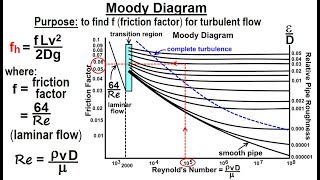
Reynolds Number: Helps categorize flow types and determine friction factors.
Examples & Applications
Calculating the total head loss in a pipe when given the friction factor, length, and pipe diameter.
Determining required pump horsepower by using the elevation difference and computed head losses.
Memory Aids
Interactive tools to help you remember key concepts
Rhymes
For losses in flow, friction won't slow, with factors in tow, keep energy flow.
Stories
Imagine a river entering a narrow canyon, it swirls and slows down due to the rocks on the sides. This is like our entry loss—fluid slows before it speeds up again at the exit.
Memory Tools
F-H-L-D-R: Friction factor, Head loss, Length, Diameter, Reynolds number.
Acronyms
P.E.T
Power = Elevation change + Total losses to remember pump horsepower requirements.
Flash Cards
Glossary
- Friction Factor
A dimensionless quantity that represents the effect of friction on the flow of fluid in pipes.
- Total Head Loss
The total reduction in the energy per unit weight of fluid due to friction, turbulence, and fittings.
- DarcyWeisbach Equation
An empirical relationship used to calculate the pressure loss due to friction in a pipe.
- Loss Coefficient
A number that quantifies the loss of energy associated with fittings and transitions in a piping system.
- Moody’s Chart
A graphical representation used to determine the friction factor based on Reynolds number and relative roughness.
- Reynolds Number
A dimensionless quantity that helps predict flow patterns in different fluid flow situations.
Reference links
Supplementary resources to enhance your learning experience.