
Calculation of Friction Factors from Moody's Chart
Enroll to start learning
You’ve not yet enrolled in this course. Please enroll for free to listen to audio lessons, classroom podcasts and take practice test.
Interactive Audio Lesson
Listen to a student-teacher conversation explaining the topic in a relatable way.
Introduction to Friction Factors
🔒 Unlock Audio Lesson
Sign up and enroll to listen to this audio lesson

Today, we will start our exploration into friction factors, particularly how they are derived from Moody's Chart. Can someone tell me why friction factors are important in fluid flow?

Friction factors help us determine how much energy is lost due to friction in pipes, right?
Exactly, great answer! Remember the acronym 'FLEEA' - Friction Loss Evaluates Energy Adaptation. Energy losses are critical for designing effective piping systems. Now, what variables do you think influence the friction factor?

The length and diameter of the pipe, as well as its roughness, I think?
Correct! Additionally, the flow characteristics and the fluid properties also play a roles. Let's look into those in detail during our calculations.
Understanding the Darcy-Weisbach Equation
🔒 Unlock Audio Lesson
Sign up and enroll to listen to this audio lesson

Now let's discuss the Darcy-Weisbach equation, which is pivotal for calculating energy losses in pipes. Can anyone state what the equation looks like?

Isn't it hL = f (L/D) (V²/2g)?
Yes! And remember, 'hL' stands for head loss, 'f' for friction factor, and so forth. A mnemonic is 'Hot Lemons Feed Vigorously at G,' to recall the components of this formula. What do you think will happen if we increase the pipe length?

The head loss would increase, right?
Exactly right! Longer pipes increase resistance, leading to higher energy losses.
Calculating Friction Factors from Moody's Chart
🔒 Unlock Audio Lesson
Sign up and enroll to listen to this audio lesson
Let's move on to calculating friction factors using Moody's Chart. What information do we need to consult the chart effectively?
We need the Reynolds number and the relative roughness of the pipe?
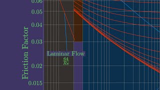
Correct! The mnemonic 'Reynolds Rules Roughness' can help you remember. Now, if I tell you our Reynolds number is 145,000, what does that tell you about our flow regime?
It indicates turbulent flow since it's above 4,000.
Perfect! Turbulent flow usually dictates different friction factor calculations. Let's practice using some example values.
Applying the Calculations to Practical Problems
🔒 Unlock Audio Lesson
Sign up and enroll to listen to this audio lesson
Now that we have our friction factor, how can we apply this knowledge to real-world problems?
By calculating the pump horsepower needed to overcome these losses.
Yes, and remember the formula Power = (flow rate x head loss) / efficiency. What's our estimated efficiency if we need 4.3 hp?
Assuming we're at 70% efficiency, we adjust accordingly.
Great! That’s how we connect theory to practice, ensuring our designs are efficient.
Summary and Review
🔒 Unlock Audio Lesson
Sign up and enroll to listen to this audio lesson
To conclude today's session, can someone summarize what we have learned about friction factors?
We learned how to use the Darcy-Weisbach equation and compute the friction factor from Moody's Chart!
Exactly! Keep in mind 'DREAM' - Darcy, Reynolds, Entry losses, Adaptation of formula, and Moody's Chart. Keep these concepts in mind as we proceed!
Introduction & Overview
Read summaries of the section's main ideas at different levels of detail.
Quick Overview
Standard
This section elaborates on the importance of calculating friction factors from Moody's Chart for determining head losses in fluid systems. It presents a clear application of the Darcy-Weisbach equation to analyze energy losses in pipe flow, demonstrating the process with specific examples and assumptions relevant to different configurations.
Detailed
In this section, we delve into the calculation of friction factors from Moody's Chart, focusing on the parameters needed for accurate computations. The friction factor is a critical element in assessing total head losses in fluid systems, which is influenced by pipe length, diameter, roughness, and head loss coefficients during entry and exit. We explore the Darcy-Weisbach equation for quantifying these head losses, highlighting how to incorporate velocity head losses. The theoretical insights are followed by practical examples, including computations involving specific pipe configurations and how design considerations impact the required pump horsepower. The section underscores the role of experimental data in determining loss coefficients and offers methods for calculating friction factors while reinforcing the significance of accurate hydraulic design in engineering.
Youtube Videos
![Turbulent Flow: Moody Chart [Fluid Mechanics #41]](https://img.youtube.com/vi/tISdp_394Bw/mqdefault.jpg)

Audio Book
Dive deep into the subject with an immersive audiobook experience.
Friction Factor and Given Parameters
Chapter 1 of 5
🔒 Unlock Audio Chapter
Sign up and enroll to access the full audio experience
Chapter Content
So the friction factors data what is given it length of the pipe the diameters and total head losses. Given:
- friction factor = 0.04
- Length (pipe) = 2000 m
- Diameter = 0.2 m
- Total head loss = 8 m
Assume:
- Loss coefficient (entry) = 0.5
- Loss coefficient (exit) = no loss (=1)
Detailed Explanation
In this chunk, we discuss the important parameters used in calculating friction factors, which are required to determine head loss in pipe systems. The friction factor is a value used in hydraulic calculations to quantify friction losses due to the pipe's internal surface. The length and diameter of the pipe are crucial because they directly affect how fluid flows through it. Additionally, the loss coefficients at entry (0.5) and exit (1) represent how much energy is lost as fluid enters and exits the pipe.
Examples & Analogies
Imagine you are sliding down a slide. The length and width of the slide play a big role in how smoothly you slide down versus if you were going down a rough, narrow tube. In fluid mechanics, the friction factor is like the texture of that surface—it determines how easy or hard it is for the water to travel through the pipe.
Darcy Weisbach Equation Application
Chapter 2 of 5
🔒 Unlock Audio Chapter
Sign up and enroll to access the full audio experience
Chapter Content
Now we apply the Darcy Weisbach equations to compute what is energy losses for the major losses or the pipe flow because of the frictions components and the minor losses. Head loss (Darcy Weisbach Equation):
Total head loss:
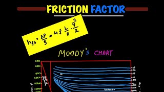
$$ h_{loss} = f \frac{L}{D} \frac{V^2}{2g} $$
Where:
- \( f \) is the friction factor
- \( L \) is the length of the pipe
- \( D \) is the diameter of the pipe
- \( V \) is the flow velocity,
- \( g \) is the acceleration due to gravity.
Detailed Explanation
In this section, we apply the Darcy Weisbach equation, a fundamental equation in fluid mechanics, to calculate the head loss due to friction in a flowing fluid. The total head loss in a pipe is calculated using the friction factor and the properties of the pipe, which helps us understand how much energy is lost as the fluid moves through the pipe. This account of energy loss is crucial for designing efficient fluid systems.
Examples & Analogies
Think of this equation like a roller coaster track. The longer and steeper the track (like the length and slope of the pipe), the more energy (or height) you lose as you're traveling downhill. The friction factors in the equation act like brakes on the roller coaster, slowing it down and causing it to lose more energy.
Solving for Velocity and Head Loss
Chapter 3 of 5
🔒 Unlock Audio Chapter
Sign up and enroll to access the full audio experience
Chapter Content
By substituting these and we can get it the series of equations like this and substituting the value you will get a quadratic functions and solving that you will get the velocity. So if you look at these problems is quite easy. Only you have to remember about the coefficients, the factors what we use it, the loss coefficient or factors what we use for computing the entry loss and the exit loss.
Detailed Explanation
In this portion, we see that by inserting the values into our derived equations, we can solve for the flow velocity. The process may yield quadratic equations which can be solved to find the specific value of flow velocity, which is integral in calculating the overall head loss in the system. Remembering the loss coefficients helps simplify the calculations.
Examples & Analogies
It's like solving a puzzle. You can see how the pieces (the values we substitute) fit together to reveal the picture (the flow velocity and head loss). The loss coefficients are like the guidelines you follow to make sure you place the pieces in the right spots.
Overall Loss Components and Pump Requirements
Chapter 4 of 5
🔒 Unlock Audio Chapter
Sign up and enroll to access the full audio experience
Chapter Content
The last examples, let us have a it is slight bit a design problems could be consider it where you have the two reservoirs okay you have a entrance and exit. The water density and the kinematic viscosity is given to us. Compute the pump horsepower required and the K value given for the bend is 0.25. Regular 90 degree elbow is 0.95. Open globe valve is 6.9. Half closed gate valve is 2.7.
Detailed Explanation
Here, we consider a slightly more complex scenario involving two reservoirs connected by a pipe, where we evaluate various components that can cause losses (like bends, elbows, and valves). We also need to compute the pump horsepower necessary to overcome these losses. Each component has a specific loss coefficient, which quantifies its impact on the fluid flow.
Examples & Analogies
Think of this setup like a complicated water slide park. Each turn (bend and elbow) and gate (valve) in the slide slows down the water, just like how the fluid dynamics specifics slow down water flow in pipes. To keep the thrill of the water slide consistent (or maintain the flow), we need to know how powerful (horsepower) our pumps need to be to counter the slowdowns caused by these obstacles.
Calculating Pumping Power Requirement
Chapter 5 of 5
🔒 Unlock Audio Chapter
Sign up and enroll to access the full audio experience
Chapter Content
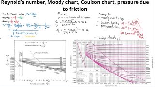
This is what in general design we do it to compute the Reynolds numbers. Then we for a given roughness factors, we can compute it what will be the R. Get this from chart what will be the friction factors value. By conducting a series of experiment any of the industry they give these value what is the range of the energy loss coefficients for the bend, valve, elbow it is given generally in a any pipe manufacturing company.
Detailed Explanation
In this part, we explore how to compute important parameters such as Reynolds numbers, which indicate the flow regime, and how to find corresponding friction factors using Moody's chart. The utilization of empirical data from industries ensures that our coefficients for various components reflect real-world applications, facilitating more accurate designs.
Examples & Analogies
It's like getting the user manual for a new appliance. The manual helps you understand how to best use it based on the testing done by the manufacturer. In our case, the experiments done in the industry provide the necessary data for flowing water through pipes.
Key Concepts
-
Friction factors are crucial for calculating head losses in fluid systems.
-
The Darcy-Weisbach equation relates friction loss to physical parameters of the system.
-
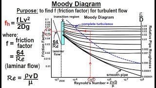
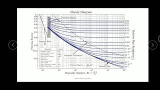
Moody's Chart provides a practical method for determining friction factors based on pipe roughness and flow conditions.
Examples & Applications
If you have a friction factor of 0.04, a pipe length of 2000 m, and a diameter of 0.2 m, you can calculate the energy losses using the Darcy-Weisbach equation.
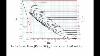
For a pipe that has turbulent flow (Reynolds number > 4000), consult Moody’s Chart to find the appropriate friction factor for the specific diameter and roughness.
Memory Aids
Interactive tools to help you remember key concepts
Rhymes
In pipes so long and short, Friction factors give us support.
Stories
Imagine a water pipe, long and rough, the water slows down; friction makes it tough.
Memory Tools
FLEEA: Friction Loss Evaluates Energy Adaptation.
Acronyms
DRIVE
Darcy
Reynolds
Influences of Fluid properties
Velocity head
Energy loss.
Flash Cards
Glossary
- Friction Factor
A dimensionless quantity used in fluid dynamics to quantify the resistance to flow due to friction in a fluid flowing through a conduit.
- DarcyWeisbach Equation
An equation used to calculate head loss due to friction in a pipe, expressed as hL = f (L/D) (V²/2g).
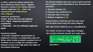
- Moody's Chart
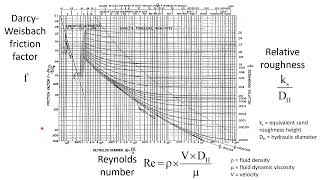
A graphical representation that shows the relationship between the Reynolds number and friction factor for various pipe roughness.
- Reynolds Number
A dimensionless number used to predict flow patterns in different fluid flow situations, calculated using fluid velocity, characteristic length (pipe diameter), and viscosity.
- Head Loss
The energy loss of a fluid as it moves through a pipe due to friction and other factors.
Reference links
Supplementary resources to enhance your learning experience.