
Pumping Requirements and Energy Losses
Enroll to start learning
You’ve not yet enrolled in this course. Please enroll for free to listen to audio lessons, classroom podcasts and take practice test.
Interactive Audio Lesson
Listen to a student-teacher conversation explaining the topic in a relatable way.
Understanding Friction Factors
🔒 Unlock Audio Lesson
Sign up and enroll to listen to this audio lesson

Today, we will start with friction factors. They play a critical role in calculating energy losses. Can anyone tell me what factors might contribute to friction in a pipe system?

I think the length and diameter of the pipe affect it.
Exactly! Longer pipes and larger diameters generally reduce friction. Remember, friction factor is influenced by surface roughness too. We have friction factors ranging from 0 to 1.0. For a typical pipe, a friction factor of 0.04 is common. What would increase friction?

Rough surfaces and bends in the pipe can increase friction.
Right! Think of how rough surfaces might disturb the flow. So to summarize, the key points for friction factors include length, diameter, and surface roughness. Use the acronym 'LDS' for remembering these factors!
Darcy-Weisbach Equation
🔒 Unlock Audio Lesson
Sign up and enroll to listen to this audio lesson

Now that we have a good grasp of friction factors, let’s talk about the Darcy-Weisbach equation. Who remembers its form?

Isn't it related to head loss in a pipe due to friction?
Correct! The Darcy-Weisbach equation helps us quantify the head loss due to friction. It's given by the formula h_f = f * (L/D) * (V^2/2g), where 'h_f' is head loss. Can anyone explain what each symbol represents?

L is length, D is diameter, V is flow velocity, g is acceleration due to gravity, and f is the friction factor.
Great job! Remember that understanding this equation is crucial for designing efficient piping systems. Let’s tie this to our earlier acronym 'LDS' to include 'h_f' for losses!
Application in Design Problems
🔒 Unlock Audio Lesson
Sign up and enroll to listen to this audio lesson
Now let's apply what we’ve learned with a design example. Consider a pipe system connecting two reservoirs. What should we take into account when calculating the pump horsepower needed?
We should consider both major and minor losses, and the height difference between the two reservoirs.
Exactly! We also need to include the loss coefficients for entry and exit points of the system. Understanding these components ensures effective pump selection. How do we factor in the kinematic viscosity here?
We need to calculate the Reynolds number first to determine the friction factor from Moody's chart.
Well done! Calculating the Reynolds number is essential. Keep in mind the complexity of real systems, which can involve several types of losses. Always refer back to our framework: 'LEAD', representing Losses, Entry, Area, and Design!
Introduction & Overview
Read summaries of the section's main ideas at different levels of detail.
Quick Overview
Standard
In this section, we explore the relationship between pumping requirements and energy losses in liquid transport systems. Key concepts include friction factors, loss coefficients for pipe entries and exits, and how to compute total head loss using the Darcy-Weisbach equation. Additionally, design examples are presented to illustrate the practical implications of these concepts in engineering applications.
Detailed
Pumping Requirements and Energy Losses
This section introduces the concept of energy losses in a fluid transport system, particularly through pipes, which can significantly affect the efficiency of pumping systems. The Darcy-Weisbach equation serves as the primary tool for calculating these energy losses, incorporating friction factors based on pipe characteristics and flow conditions. Key points include:
- Friction Factors: Defined based on pipe length, diameter, and flow conditions. An example provides a friction factor of 0.04 for a 2000 m long and 0.2 m diameter pipe with a total head loss of 8 m.
- Loss Coefficients: Discussed for entries and exits of pipes. For instance, the entry loss coefficient is assumed to be 0.5, while the exit contributes no additional loss (coefficient of 1).
- Darcy-Weisbach Equation: This fundamental equation calculates total head loss due to friction and other minor losses. The equation helps derive necessary parameters for evaluating how much energy is needed for pumping fluids through a system.
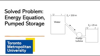
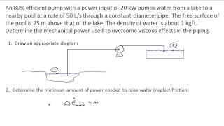
- Design Application: A design example is presented, demonstrating calculations for a two-reservoir system connected by a pipe, taking into account both major and minor losses, as well as pump horsepower requirements.
- Moody’s Chart: Important for determining friction factors based on Reynolds number and pipe roughness; shown as critical for design calculations.
Through step-by-step numerical examples, learners gain insights into finding pumping requirements, understanding energy losses, and applying theoretical principles to real-world scenarios.
Youtube Videos


Audio Book
Dive deep into the subject with an immersive audiobook experience.
Friction Factors and Head Losses
Chapter 1 of 6
🔒 Unlock Audio Chapter
Sign up and enroll to access the full audio experience
Chapter Content
So the friction factors data what is given it length of the pipe the diameters and total head losses. The loss coefficient in terms of velocity head as you know it at the exit we consider as 1, at the entry we consider 0.5. The half of the velocity head losses at entry levels and at the exit level total velocity head what we lost it at the exit level.
Detailed Explanation
In this chunk, we discuss friction factors, which are crucial for understanding head losses in fluid transport systems. The friction factor is dependent on the pipe's length, diameter, and overall head losses. Specifically, the loss coefficient at the pipe's entry is considered to be 0.5, while the exit is taken as 1. This means that half of the velocity head is lost at the entry, whereas the total velocity head loss at the exit is the sum of losses experienced from entry to exit.
Examples & Analogies
Think of water flowing through a garden hose. The longer the hose (similar to longer pipe length), the more 'friction' there is due to the hose's inner walls affecting the flow. When water enters the hose, it experiences a slight slowdown, akin to the entry loss, and when it exits, there's still some remaining speed, which is akin to the exit loss.
Applying Darcy Weisbach Equation
Chapter 2 of 6
🔒 Unlock Audio Chapter
Sign up and enroll to access the full audio experience
Chapter Content
Now we apply the Darcy Weisbach equations to compute what is energy losses for the major losses or the pipe flow because of the friction components and the minor losses.
Detailed Explanation
The Darcy Weisbach equation is a fundamental calculation used to estimate energy losses due to friction in pipes. By applying this equation, we can quantify both major losses (due to long, straight sections of pipe) and minor losses (due to fittings, bends, or changes in diameter). This understanding allows engineers to design more efficient plumbing systems by minimizing energy losses.
Examples & Analogies
Imagine using a water slide that has smooth transitions vs. one with numerous bends and turns. The smooth slide (analogous to straight pipe sections) allows for a quicker ride (less energy loss), while the one with many turns requires more effort to slide down (more energy loss). Engineers need to account for these differences to ensure water flows efficiently.
Calculation of Energy Losses
Chapter 3 of 6
🔒 Unlock Audio Chapter
Sign up and enroll to access the full audio experience
Chapter Content
By substituting these and we can get it the series of equations like this and substituting the value you will get a quadratic functions and solving that you will get the velocity.
Detailed Explanation
Here, the process of substituting known values into the Darcy Weisbach equation involves algebraic manipulation that can lead to quadratic equations. By solving these equations, we can determine the actual velocity of the fluid flowing through the pipe, which is essential for calculating the overall system efficiency and performance.
Examples & Analogies
Visualize trying to calculate the speed of a car going along a winding road. Just as one must consider the road’s turns and length to figure out speed (analogous to solving equations to find velocity), engineers must consider pipe characteristics to optimize fluid flow.
Pressure Loss Calculations
Chapter 4 of 6
🔒 Unlock Audio Chapter
Sign up and enroll to access the full audio experience
Chapter Content
If a roughness ratio of this pipe is given it is this part. Compute the pump horsepower required and the K value given for the bend is 0.25. Regular 90 degree elbow is 0.95. Open globe valve is 6.9. Half closed gate valve is 2.7.
Detailed Explanation
In designing pumping systems, engineers must consider the pipe's roughness, which affects friction and, correspondingly, pressure losses. The coefficients (K values) for bends and valves inform how much energy loss occurs at these points in the system. Accurate calculations of these losses are critical to ensure that pumps provide sufficient power to maintain desired flow rates.
Examples & Analogies
Imagine a series of obstacles in a race (like bends and gates). Each obstacle slows a runner down (contributing to energy losses). Knowing the impact of each obstacle helps the coach determine how fast the runner needs to be to reach the finish line (just like calculating required pump horsepower for optimal performance).
Determining Pump Requirements
Chapter 5 of 6
🔒 Unlock Audio Chapter
Sign up and enroll to access the full audio experience
Chapter Content
Now we will go to the next what we will do it is very simple things that we are applying this energy equations head loss and this part since two part V , V , if I put the energy losses V , V is zero, and solving this pumping head.
Detailed Explanation
The next step is to derive the pumping requirements by applying energy equations to account for both major and minor losses. By setting specific variables zero (such as velocities at different points), we simplify the equations to find the head requirement at the pump, which informs how high the pump must lift the fluid.
Examples & Analogies
Considering a water fountain, the pump must push water high enough to reach the desired height of the jet. If we know the height it must lift (analogous to the head requirement), we can determine the pump's power needed to ensure it functions correctly.
Calculating Power Requirements
Chapter 6 of 6
🔒 Unlock Audio Chapter
Sign up and enroll to access the full audio experience
Chapter Content
The conversion factor is 1 hp = 746 W. Therefore 3200 / 746 gives us the power requirement.
Detailed Explanation
To calculate how much power (in horsepower) the pump needs to lift water to a given height, we first determine the total head and consider the efficiency of the pump system. Using the conversion between watts and horsepower is critical for ensuring the pump's ability is well-understood in practical (and often industry-standard) terms.
Examples & Analogies
Think of how your car's engine needs a specific horsepower to operate efficiently. If the car isn’t powerful enough (like our pump), it won't go up steep hills (lifting the water required). Understanding horsepower helps car manufacturers know the best engine to use for a particular model, much like how engineers select pumps for different applications.
Key Concepts
-
Friction Factors: These are essential for calculating energy loss due to friction in fluid flow.
-
Loss Coefficient: A value that estimates the energy loss associated with pipe fittings and entries/exits.
-
Darcy-Weisbach Equation: A critical equation used to relate head loss to friction in pipes.
-
Reynolds Number: Important for determining flow regime and corresponding friction factors from Moody's chart.
Examples & Applications
An example showed that for a friction factor of 0.04, length of the pipe 2000 m, and diameter 0.2 m, the total head loss was calculated to be 8 m.
Another example calculated the horsepower needed for pumping across a height of 30 m, factoring in both major and minor losses from various fittings.
Memory Aids
Interactive tools to help you remember key concepts
Rhymes
In a pipe where water flows, friction rises as length grows!
Stories
Imagine a water slide – the longer it is and the bumpier it gets, the harder it is to slide down smoothly, just like in a piping system where friction increases energy loss.
Memory Tools
Remember 'FLEED' for head loss terms: Friction, Length, Entry, Diameter.
Acronyms
Use 'LEAD' to recall piping system components
Losses
Entry
Area
Design.
Flash Cards
Glossary
- Friction Factor
A dimensionless quantity used to describe the resistance to flow in a pipe due to friction.
- DarcyWeisbach Equation
An equation used to calculate pressure loss or head loss due to friction in fluid flow.
- Head Loss
The reduction in total mechanical energy of the fluid as it moves through a pipeline.
- Loss Coefficient
A coefficient that quantifies the energy loss in a system due to disturbances in the flow.
- Reynolds Number
A dimensionless number used to predict flow patterns in different fluid flow situations.
Reference links
Supplementary resources to enhance your learning experience.