
Friction Factors and Energy Losses
Enroll to start learning
You’ve not yet enrolled in this course. Please enroll for free to listen to audio lessons, classroom podcasts and take practice test.
Interactive Audio Lesson
Listen to a student-teacher conversation explaining the topic in a relatable way.
Understanding Friction Factors
🔒 Unlock Audio Lesson
Sign up and enroll to listen to this audio lesson

Today, we're going to explore friction factors in fluid flow. Can anyone tell me why friction is important in pipes?

Friction impacts how easily fluid can flow, right?
Exactly! Friction causes energy losses in the system. Now, does anyone know the typical values of friction factors for different flows?

Is it different for laminar and turbulent flows, teacher?
Yes! That's a vital point. Laminar flows have lower friction factors compared to turbulent flows. Remember this acronym: 'FLT' — 'Friction in Laminar Turbulent' — it will help you remember the relation between flow types and friction.

Can you explain how we calculate these friction factors?
Of course! We can use empirical formulas or charts like Moody's chart. Remember to keep track of flow characteristics such as Reynolds number!
In summary, friction factors significantly affect fluid flow, and knowing how to compute them will help us manage energy losses effectively.
Total Head Loss Calculation
🔒 Unlock Audio Lesson
Sign up and enroll to listen to this audio lesson

Now, let's dive into how we calculate total head loss using the Darcy-Weisbach equation. Can someone recall the equation?
Isn’t it something like h = f (L/D) (V²/2g)?
Close! It’s h = f * (L/D) * (V²/2g), where h is the head loss, f is the friction factor, L is length, D is diameter, V is the flow velocity, and g is the acceleration due to gravity. Now, what values do we have for our example problem?

We have L = 2000 m, D = 0.2 m, and f = 0.04.
Great! Now, let’s plug those into the equation. What do we get?
We should calculate some loss values! That's how we visualize energy loss due to friction.
Exactly! Ensuring we understand these calculations allows us to design better systems and reduce unnecessary energy expenditures. Remember to practice these calculations during your study.
Entry and Exit Losses
🔒 Unlock Audio Lesson
Sign up and enroll to listen to this audio lesson
Now, let’s discuss minor losses, specifically entry and exit losses. What are the typical coefficients for these losses?
For entry, it's 0.5, and for exit, it's usually considered 1, right?
Perfect! These coefficients account for how fluid behaves when entering and exiting pipes. Why do we care about these losses in design?
Because they help us calculate the total energy loss in the system, so we can size our pumps properly!
Absolutely! Understanding these losses ensures that systems are efficient. So, how would you calculate total head loss if we include these components?
We would add the losses from entry and exit to the major losses calculated before!
Yes! That’s a key concept. Remember, major and minor losses together give us the total loss, which is crucial for pump sizing and system efficiency.
Practical Application Scenarios
🔒 Unlock Audio Lesson
Sign up and enroll to listen to this audio lesson
Let’s move on to some practical scenarios. If we have two reservoirs with various minor losses like valves and bends, how do we approach calculating pump horsepower?
We need to account for all types of losses! Every valve and bend contributes to energy loss, right?
Exactly! Each component has an associated loss coefficient that we need to add cumulatively. Can anyone tell me the given loss coefficients for a typical elbow or valve?
For a 90-degree elbow, it's 0.95! I remember that from discussions.
Well done! If we sum all the losses, how can we ensure we calculate the necessary horsepower to maintain flow?
We convert the head requirement into horsepower using the equation for power based on weight and flow!
Exactly! This real-world application helps you understand why theoretical knowledge is essential in practical engineering.
Introduction & Overview
Read summaries of the section's main ideas at different levels of detail.
Quick Overview
Standard
The section outlines the relationship between friction factors, pipe length, and diameter in calculating total head losses. It provides a detailed look at Darcy Weisbach equations and the importance of understanding entry and exit loss coefficients in determining energy losses during fluid flow.
Detailed
Friction Factors and Energy Losses
This section covers the foundational concepts related to friction factors in fluid mechanics, particularly as it pertains to calculating energy losses in pipe flow. It begins with definitions and key coefficients, including the friction factor (given as 0.04), length of the pipe (2000 m), diameter (0.2 m), and total head loss (8 m). The various loss coefficients are introduced, particularly for entry and exit points, with entry losses considered at 0.5 and exit losses effectively null at 1.
Using the Darcy-Weisbach equation, we derive the total head loss in the pipe system, emphasizing the importance of understanding these calculations in practical scenarios, such as designing pumping systems. The section also includes context regarding the major and minor losses that occur due to friction and other factors. Practical examples illustrate how to apply these concepts effectively, culminating in the need to compute specific pumping horsepower based on calculated energy requirements, showcasing an application of theoretical knowledge to real-world engineering problems.
Youtube Videos


Audio Book
Dive deep into the subject with an immersive audiobook experience.
Introduction to Friction Factors
Chapter 1 of 6
🔒 Unlock Audio Chapter
Sign up and enroll to access the full audio experience
Chapter Content
So the friction factors data what is given it length of the pipe the diameters and total head losses. The loss coefficient in terms of velocity head as you know it at the exit we consider as 1, at the entry we consider 0.5. The half of the velocity head losses at entry levels and at the exit level total velocity head what we lost it at the exit level. This is 1, this is 1.5.
Detailed Explanation
Friction factors help in determining how much energy is lost when fluid flows through a pipe. The friction factors depend on the pipe's length, its diameter, and the total head losses. Head loss refers to the reduction in total head of the fluid, which results from friction along the pipe's walls. At the exit of the pipe, the loss coefficient is considered to be 1, meaning that all the energy would be usable if there were no friction. At the entry point of the pipe, we take a loss coefficient of 0.5, which indicates that half of the energy is lost here due to entry effects.
Examples & Analogies
Imagine water flowing through a garden hose. The longer the hose, the more difficult it is for water to flow due to friction against the hose walls. Similarly, the wider the hose (larger diameter), the easier it is for water to flow with less friction. The loss coefficients provide a way to quantify this frictional loss of energy at both the entry and exit points.
Application of the Darcy Weisbach Equation
Chapter 2 of 6
🔒 Unlock Audio Chapter
Sign up and enroll to access the full audio experience
Chapter Content
Now we apply the Darcy Weisbach equations to compute what is energy losses for the major losses or the pipe flow because of the frictions components and the minor losses.
Detailed Explanation
The Darcy Weisbach equation is used to calculate head loss due to friction in a pipe. This equation takes into account the friction factor, the pipe's length, the pipe's diameter, and the fluid's velocity. By plugging in the known values into this equation, we can determine the total energy lost due to these frictional forces. The equation simplifies complex variables into a manageable calculation that tells us how much energy we need to compensate for friction losses.
Examples & Analogies
Consider a water slide. The longer the slide, the more water resistance the sliders face, which means they slow down. The Darcy Weisbach equation would help determine how much water pressure (or energy) you need at the top of the slide to ensure that sliders reach the bottom quickly even after accounting for losses due to friction against the slide's material.
Understanding Loss Coefficients
Chapter 3 of 6
🔒 Unlock Audio Chapter
Sign up and enroll to access the full audio experience
Chapter Content
By substituting these and we can get it the series of equations like this and substituting the value you will get a quadratic functions and solving that you will get the velocity.
Detailed Explanation
Loss coefficients are vital for solving equations related to fluid flow, particularly in determining how different components in a piping system affect overall flow rates. When we input these coefficients into the Darcy Weisbach equation, they contribute to a set of equations that often yield quadratic functions. Solving these equations indicates the fluid's velocity at various points in the system, which is essential for understanding overall flow behavior.
Examples & Analogies
Imagine you are trying to calculate the speed of a car as it moves through a winding road with different curves and environments. The loss coefficients represent various road conditions—like sharp turns or rough terrains—that affect how fast the car can go. By factoring in these conditions, we can accurately estimate the car's velocity throughout the journey.
Energy Loss Components
Chapter 4 of 6
🔒 Unlock Audio Chapter
Sign up and enroll to access the full audio experience
Chapter Content
The exit loss is total velocity head. Half of the velocity head we use it to as a loss at the entry level. That is the things, otherwise these problems quite a numerical problems to solve these ones.
Detailed Explanation
Energy loss in a piping system can be attributed to both entry and exit losses. The total exit loss is associated with how much of the velocity head is available when fluid exits a pipe. At the entry point, we can lose up to half of that velocity head. Understanding these concepts allows us not only to determine how much energy we lose but also to adjust our systems accordingly to ensure sufficient energy is supplied to maintain flow.
Examples & Analogies
Think of a water balloon launching through a tube. As it enters the tube, some force is lost due to its initial entry (entry loss) into the tube, while also losing some force as it exits (exit loss). If we can quantify these losses, we can design the tube or modify how we launch the balloon better to maintain the desired force for distance.
Calculating Pump Horsepower
Chapter 5 of 6
🔒 Unlock Audio Chapter
Sign up and enroll to access the full audio experience
Chapter Content
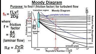
Since here the roughness factor is given to us, we need to compute the friction factors from Moody’s chart which needs Reynolds numbers. So first let us compute what will be the average velocity and what could be the Reynolds numbers for this flow.
Detailed Explanation
To determine the necessary horsepower for a pump in a system, we need to understand the roughness of the pipe and its impact on friction. This involves calculating the Reynolds number, which indicates the flow regime—whether the flow is laminar or turbulent. The Moody chart helps us relate these numbers to the friction factor, allowing us to calculate energy losses and the horsepower required to overcome these losses efficiently.
Examples & Analogies
When driving, if you're on a smooth highway, you can achieve high speeds with less energy. If you're on a rough gravel road, it takes much more energy (power) to maintain that speed. Similarly, the roughness of a pipe influences how much energy (horsepower) a pump needs to keep fluids moving effectively.
Final Overview and Power Requirements
Chapter 6 of 6
🔒 Unlock Audio Chapter
Sign up and enroll to access the full audio experience
Chapter Content
This is the loss component and this is what the elevation, the potential head what we need it from 6 meter to 36 meters.
Detailed Explanation
In practical applications, understanding the total energy needed for a pumping system involves calculating both the potential head—the difference in elevation between two points—and the friction losses throughout the system. The total head required will be higher than the potential head alone because of the energy lost due to friction. Once we calculate this total energy requirement, we can then find out how much power (in horsepower) the pump must provide to achieve the desired flow rate against these energy losses.
Examples & Analogies
Oftentimes, when climbing a hill while riding a bicycle, you need to pedal harder to maintain your speed because of the hill's elevation and the friction with the road. Similarly, pumps must increase power output to counteract elevation differences and frictional losses as water flows through pipes.
Key Concepts
-
Friction Factor: Fundamental for understanding losses in pipe flow.
-
Total Head Loss: Sum of all energy losses in a fluid system.
-
Darcy-Weisbach Equation: A critical equation for engineers to calculate head loss.
-
Minor Losses: Essential for accurate calculations of energy requirements and pump sizing.
-
Loss Coefficient: Determines head loss at entry and exit points in piping systems.
Examples & Applications
Calculating the total head loss in a 2000 m long pipe with a diameter of 0.2 m using a friction factor of 0.04.
Assessing the energy requirements for a pumping system with multiple valves and bends, factoring in minor losses for accurate horsepower needs.
Memory Aids
Interactive tools to help you remember key concepts
Rhymes
In pipes that twist and turn, minor losses we discern; entry, exit, they all share, calculating losses, do take care.
Stories
Imagine water flowing through a pipe with a narrow entry, where it hesitates and loses energy. As it travels, it hits bends that slow it down even more, and upon exiting, it heads up to reservoirs, mindful of each energy cost.
Memory Tools
Remember: 'FHT' — Friction, Head loss, Total loss. Keep these in mind when designing piping systems.
Acronyms
LEAD
Length
Entry
Area
Discharge. These factors characterize the flow and losses in pipe systems.
Flash Cards
Glossary
- Friction Factor
A dimensionless number used to calculate pressure loss due to friction in fluid flow.
- Total Head Loss
The total energy loss in a fluid system, usually represented in terms of height of fluid (meters), due to friction and other losses.
- DarcyWeisbach Equation
An equation used to calculate the head loss due to friction in a pipe.
- Minor Losses
Energy losses due to fittings, bends, valves, and other components in a fluid system.
- Entry Loss Coefficient
A coefficient used to quantify head loss when fluid enters a pipe.
- Exit Loss Coefficient
A coefficient that quantifies the head loss when fluid exits a pipe.
Reference links
Supplementary resources to enhance your learning experience.