
Design Problems in Fluid Mechanics
Enroll to start learning
You’ve not yet enrolled in this course. Please enroll for free to listen to audio lessons, classroom podcasts and take practice test.
Interactive Audio Lesson
Listen to a student-teacher conversation explaining the topic in a relatable way.
Understanding Friction Factors
🔒 Unlock Audio Lesson
Sign up and enroll to listen to this audio lesson

Let's start by discussing friction factors in fluid mechanics. The friction factor plays a crucial role in determining the energy losses in a pipe system. What do you think influences the friction factor?

I think it depends on the pipe's material and how smooth it is.
Great! Yes, the pipe's roughness and diameter, along with the fluid's velocity, significantly affect the friction factor. We often refer to Moody's chart to find this relationship. Can anyone explain what other factors we may consider?

Maybe the length of the pipe and the viscosity of the fluid?
Correct! The pipe length and fluid properties, such as density and viscosity, are fundamental in these calculations. Remember the acronym R-F-V-L for 'Roughness, Fluid, Velocity, Length' as key influencers on the friction factor.
Calculating Head Loss
🔒 Unlock Audio Lesson
Sign up and enroll to listen to this audio lesson

Now, let’s explore how to calculate the head loss in a pipe using the Darcy-Weisbach equation. Can someone tell me the equation?

Is it something like h_loss equals f times L over D times V squared over 2g?
Exactly! That’s the right formula. The variables here are important: 'f' is the friction factor, 'L' is the pipe length, 'D' is the diameter, and 'V' is the velocity of the fluid. How do the loss coefficients at entry and exit affect this calculation?

The entry loss might reduce the total energy loss because it's less than the exit loss?
You're on point! Entry loss coefficients typically lessen head loss, while the exit loss may be more extensive. Remember the coefficients you learned earlier—0.5 and 1 for entry and exit losses respectively.
Example Problem with Two Reservoirs
🔒 Unlock Audio Lesson
Sign up and enroll to listen to this audio lesson
Let’s dive into a design problem involving two reservoirs connected by a pipe. What key parameters do we need to identify?
We need the pipe length, diameter, and the total head loss between the reservoirs.
Correct! For this example, we have a 120-meter-long pipe with a diameter of 0.05 meters. Let’s calculate the pumping horsepower needed. Can anyone walk me through the steps?
First, we need to determine the flow velocity and Reynolds number, right?
Yes! The flow velocity is paramount. Can anyone recall how to find the Reynolds number with the given parameters?
We divide the density and velocity by the viscosity, right?
You're correct. Once we compute the Reynolds number, we can find the friction factor from Moody's chart, then calculate the total energy losses and finally determine the necessary horsepower to pump the fluid.
Understanding Minor Losses
🔒 Unlock Audio Lesson
Sign up and enroll to listen to this audio lesson
Minor losses can significantly impact our design calculations. What are some examples of minor losses we need to consider?
Things like valves, bends, and fittings in the pipe system.
Exactly! Minor losses can account for a considerable fraction of total energy loss. The K values for valves and bends are crucial in these calculations.
How do we calculate these minor losses?
Great question! We use the equation: h_minor = K * (V² / 2g). Each fitting or valve has its own K value, which you will need to look up. Who remembers what the K value was for a 90-degree elbow?
I think it's around 0.95.
That's right! Remembering these values and how they fit into our loss calculations is critical for efficient design.
Concluding Insights
🔒 Unlock Audio Lesson
Sign up and enroll to listen to this audio lesson
To conclude our discussions today, can anyone summarize what we've learned about energy losses in pipe systems?
We learned how to calculate major and minor losses and how to apply that to design problems involving fluid systems across elevations.
Exactly! Understanding these concepts helps us design effective and efficient fluid transport systems. Remember, always check the loss coefficients and consult resources like the Moody chart when calculating friction factors.
It’s been very helpful to connect the theory with practical examples!
I'm glad to hear that! Carry these insights into your future work in fluid mechanics.
Introduction & Overview
Read summaries of the section's main ideas at different levels of detail.
Quick Overview
Standard
This section focuses on the application of the Darcy-Weisbach equation to calculate energy losses in fluid mechanics. It explores how to compute the friction factor, the head loss due to major and minor losses, and the role of specific design problems that involve two reservoirs connected by a pipe.
Detailed
Design Problems in Fluid Mechanics
This section delves into the fundamental concepts surrounding design problems in fluid mechanics, particularly concerning energy losses in pipe flow systems. It emphasizes the Darcy-Weisbach equation as a critical tool to calculate the major and minor energy losses attributed to friction and other factors. The primary components discussed include:
- Friction Factors: The section begins by outlining the determination of friction factors based on pipe length, diameter, and total head loss, demonstrating the importance of the friction factor (given as 0.04 in the example).
- Head Loss Calculation: The input parameters for calculating head loss are provided, including velocity head losses at entry (0.5) and exit (1) points, with a form of the Darcy-Weisbach equation leading to the total head loss computation.
- Design Problem Example: A practical example is introduced—involving two reservoirs, a pipe of specified length and diameter, and the consideration of various minor losses caused by valves and bends. The challenge lies in computing the required horsepower for pumps to overcome these losses while accounting for the roughness of the pipe and using the Moody chart to determine friction factors.
- Energy Losses: The analysis incorporates both major and minor losses, with methodologies to compute energy losses across different configurations, thereby establishing the relationship between mechanical design and fluid dynamics.
Overall, this section lays a foundation for understanding the calculations required in fluid mechanics design problems, where energy efficiency and loss minimization are crucial.
Youtube Videos


Audio Book
Dive deep into the subject with an immersive audiobook experience.
Friction Factors and Head Loss
Chapter 1 of 5
🔒 Unlock Audio Chapter
Sign up and enroll to access the full audio experience
Chapter Content
The friction factors data given includes the length of the pipe, the diameters, and total head losses. The loss coefficient in terms of velocity head at the exit is considered as 1, and at the entry as 0.5.
Detailed Explanation
In fluid dynamics, the friction factor is critical for calculating head loss due to friction in pipe flow. The length of the pipe and its diameter are also essential since they directly affect how fluid flows through the pipe, impacting the energy loss experienced by the system. The exit loss coefficient reflects the energy loss when fluid exits the pipe, which is typically higher than the entry loss coefficient, indicating that it is more efficient for fluid to flow into a pipe than to exit it.
Examples & Analogies
Imagine a garden hose. The longer the hose (length) and narrower its opening (diameter), the harder it will be to push water through, leading to more energy wasted (head loss). When you turn on the hose, it's easier for water to enter than for it to exit under pressure, hence the differing loss coefficients.
Darcy-Weisbach Equation Application
Chapter 2 of 5
🔒 Unlock Audio Chapter
Sign up and enroll to access the full audio experience
Chapter Content
We apply the Darcy-Weisbach equations to compute energy losses for major losses in pipe flow due to friction components and minor losses. Total head loss is attributed to different sources.
Detailed Explanation
The Darcy-Weisbach equation is a crucial formula in fluid mechanics used to calculate the head loss due to friction in a pipe. It quantifies how much energy is lost per unit weight of fluid, translating to a drop in pressure as fluid travels through the pipe. By inputting known values such as friction factor, length of the pipe, and diameter, one can determine the total loss due to these factors. This is essential for designing efficient piping systems.
Examples & Analogies
Think of riding a bike uphill. The effort you exert is analogous to the energy used to overcome friction (head loss) as you travel along the path (pipe). Just as you feel more resistance the further you ride, fluids lose more energy over longer distances in pipes.
Design Problem Setup
Chapter 3 of 5
🔒 Unlock Audio Chapter
Sign up and enroll to access the full audio experience
Chapter Content
In this design problem, the scenario involves two reservoirs, a pipe for discharge, and various minor losses due to valves and bends. We need to compute the pump horsepower required and consider several loss coefficients.
Detailed Explanation
In engineering design, creating a system that moves fluids from one reservoir to another involves calculating the energy required to overcome losses due to friction, elevation changes, and other minor losses (like bends and valve openings). This scenario requires knowing the total head difference between the two reservoirs and understanding how losses accumulate through the system to size the pump adequately.
Examples & Analogies
Consider a water park slide. The height difference from the top to the bottom determines how fast someone can go, with each twist and turn (like bends and valves in a pipeline) slowing them down slightly. Knowing how to calculate these losses helps us design a slide that gives an exciting ride without excessive waiting at the top.
Calculating Friction Factors and Reynolds Number
Chapter 4 of 5
🔒 Unlock Audio Chapter
Sign up and enroll to access the full audio experience
Chapter Content
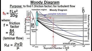
To compute the friction factors, we turn to Moody's Chart, which requires Reynolds numbers. This involves determining the average velocity and using the roughness of the pipe to find the appropriate friction coefficient.
Detailed Explanation
Moody's Chart is a visual representation that helps engineers determine the friction factor based on the flow regime (laminar or turbulent) characterized by the Reynolds number. The average velocity in the pipe is calculated first, allowing us to gauge whether the flow is smooth (laminar) or chaotic (turbulent). Depending on the roughness of the pipe material, we can obtain the appropriate friction factor to use in our calculations.
Examples & Analogies
It's similar to driving on different road surfaces. On a smooth, well-paved road (laminar flow), cars can drive quickly with less friction than on a rough, bumpy road (turbulent flow), where they must slow down due to the increased resistance.
Pump Power Requirements
Chapter 5 of 5
🔒 Unlock Audio Chapter
Sign up and enroll to access the full audio experience
Chapter Content
We derive the head requirement at the pump considering both major and minor losses calculated earlier. The power requirement translates to horsepower required to move the water the required height.
Detailed Explanation
To ensure consistent flow within a piping system, calculating the head (the height the pump needs to raise the fluid) and the associated power requirement is vital. This involves considering both the losses due to friction and how high the fluid must be lifted. The total power is converted from head required into horsepower, which helps in selecting a suitable pump for efficiency.
Examples & Analogies
Think of a balloon filled with water. If you want to lift it to a certain height, you'd need to exert a certain amount of force (power). If the pathway is clear, it's easier; if there are obstacles (like friction), you need more strength (power) to lift it as high.
Key Concepts
-
Friction Factor: A crucial value that dictates the level of energy loss due to friction in fluid flow.
-
Darcy-Weisbach Equation: A foundational equation used for calculating head loss in fluid systems.
-
Head Loss: Represents the total energy lost due to friction and other factors in pipe flow.
-
Minor Losses: Small but significant losses occurring at pipe fittings and valves that must be accounted for in design.
-
Reynolds Number: A key dimensionless number indicating flow regime, influencing friction factor calculations.
Examples & Applications
A 2000 m long pipe with a diameter of 0.2 m experiences a total head loss of 8 m due to friction.
In a fluid system involving two reservoirs, calculations show that the required power for a pump is 4.3 hp due to combined major and minor losses.
Memory Aids
Interactive tools to help you remember key concepts
Rhymes
In pipes where fluids flow with grace, friction's loss we must embrace.
Stories
Imagine a flowing river, meandering through bends and dips; as it wriggles through obstacles, it loses speed and slips. That's like our fluid in pipes, facing its own unique fights!
Memory Tools
Remember R-F-V-L: Roughness stays at the front, with Fluid, Velocity, and Length in the hunt.
Acronyms
F-H-M
Friction
Head loss
and Minor losses all are key in fluid mechanics.
Flash Cards
Glossary
- Friction Factor
A dimensionless quantity used to represent frictional losses in pipe flow due to surface roughness and flow conditions.
- DarcyWeisbach Equation
An equation used to calculate the head loss due to friction in a pipe, expressed as h_f = f * (L/D) * (V²/2g).
- Head Loss
The loss of energy due to friction and other factors as fluid flows through a pipe.
- Minor Losses
Losses in energy due to fittings, bends, valves, and other components in a pipe system.
- Reynolds Number
A dimensionless number used to predict flow patterns in different fluid flow situations.
Reference links
Supplementary resources to enhance your learning experience.