
Introduction to Verilog
Enroll to start learning
You’ve not yet enrolled in this course. Please enroll for free to listen to audio lessons, classroom podcasts and take practice test.
Interactive Audio Lesson
Listen to a student-teacher conversation explaining the topic in a relatable way.
Introduction to Verilog as a Hardware Description Language
🔒 Unlock Audio Lesson
Sign up and enroll to listen to this audio lesson

Today, we’re going to dive into Verilog! Can anyone tell me what a hardware description language is?

Is it a way to describe how digital circuits behave?
Exactly! Verilog is one of the most popular HDLs because it allows us to describe digital circuits efficiently. It's similar to C, which can make it easier for programmers to learn.

Why do we need a specific language for that?
Great question! It helps us create models that can be simulated before actual implementation, saving time and reducing errors. Remember the acronym 'SIM'—Simulate, Implement, Manage!

What about VHDL? How does Verilog compare?
Excellent point! We'll compare them, but Verilog is generally more concise than VHDL, which can make it easier to write quickly. However, VHDL is known for its strong typing.

So it's faster to write a Verilog program?
Yes, that’s right! The succinct syntax can lead to more rapid development cycles. Let's remember that: 'Verilog = Velocity in Design'! Any other questions before we proceed?
Basic Structure of Verilog Programs
🔒 Unlock Audio Lesson
Sign up and enroll to listen to this audio lesson

Next, let’s look at how a Verilog program is structured. Who remembers what the basic unit is called?
Is it called a module?
Correct! A module defines the inputs, outputs, and internal workings of a circuit. For instance, in an AND gate, how would we structure it?
Would it be something like 'module AND_GATE'?
Exactly! Following that, we’d declare the inputs and outputs. Can anyone outline how to set up inputs using Verilog syntax?
I think we’d write, 'input A, input B,'?
Perfect! So the overall structure for an AND gate would look something like this: 'module AND_GATE (input A, input B, output Y); assign Y = A & B; endmodule.' This compact form is what makes Verilog user-friendly.
Does every circuit use the same structure?
While each circuit will have specific needs, the module structure typically remains consistent, allowing for easy transitions between different projects. Remember, 'Modules Make it Manageable'!
Data Types and Operators in Verilog
🔒 Unlock Audio Lesson
Sign up and enroll to listen to this audio lesson
Let’s shift gears and talk about data types in Verilog. Who can name a few?
I believe there are wire and reg types?
Yes! We'll primarily use 'wire' for connecting components and 'reg' for storing values. It’s important to note that these types serve different purposes, which we can summarize using the mnemonic 'WIRing Connections and REgistering Values'.
What about operators? Are they different too?
Good observation! Verilog supports similar operators as VHDL—arithmetic, bitwise, and comparison operators. For instance, using '&' for AND operations and '+' for addition.
Can we write expressions directly?
Absolutely! You can write expressions directly within the 'assign' statement, such as 'assign Y = A & B;'. This allows you to make quick calculations and logic operations.
So operators help us manipulate these data types?
Precisely! They are the tools we use to define logic in our designs. Let's remember our acronym 'MHD'—Manipulate, Have Fun, and Design!
Example: Simple AND Gate Implementation
🔒 Unlock Audio Lesson
Sign up and enroll to listen to this audio lesson
To solidify our understanding, let’s look at a practical example of an AND gate in Verilog. Can anyone recall how we would start coding this?
I think we begin with 'module AND_GATE' followed by the inputs?
Correct! We then include our 'assign' statement to implement the logic. Specifically, it would look like this: 'assign Y = A & B;'—simple yet effective!
Can we see how this works in simulation?
Yes, it’s essential to simulate our designs. Using tools like ModelSim or Vivado, we can test our circuits effortlessly. Remember: 'Simulate Before You Implement!'
What if we want to expand this idea?
Great thought! We can introduce additional logic gates or even create complex systems by expanding the modules. Always think expansively in design!
So starting simple allows us to build up complexity easily?
Exactly! Remember, 'Simplicity Leads to Complexity!' Keep practicing examples, and you'll master this quickly.
Introduction & Overview
Read summaries of the section's main ideas at different levels of detail.
Quick Overview
Standard
Verilog is a key hardware description language that shares syntax similarities with the C programming language. Its concise structure allows for efficient digital circuit simulations and implementations, making it a popular choice in the industry, particularly in FPGA design.
Detailed
Introduction to Verilog
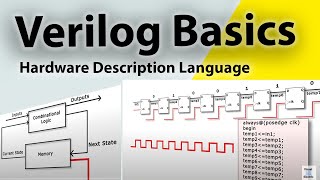
Verilog is a hardware description language (HDL) that plays a vital role in the design and simulation of digital circuits, especially in the context of FPGA (Field Programmable Gate Array) design. Its syntax closely resembles that of the C programming language, which often makes it more accessible for engineers familiar with C-style languages.
Key Features of Verilog
- Conciseness: One of the most significant advantages of Verilog is its more compact syntax compared to VHDL, allowing for quicker coding and iterations in the design process.
- Industry Usage: Widely adopted across the industry, Verilog is particularly favored for FPGA design and simulation due to its efficiency in writing complex systems.
Verilog Structure
A typical Verilog design consists of modules, which are the fundamental building blocks. Each module defines the inputs and outputs of a digital circuit along with its internal behavior. The use of 'always' blocks allows designers to define continuous behaviors based on input changes, which is essential for simulating dynamic, interactive digital systems.
In sum, understanding Verilog is crucial for anyone looking to engage deeply with circuit design and FPGA programming.
Youtube Videos

Audio Book
Dive deep into the subject with an immersive audiobook experience.
Overview of Verilog
Chapter 1 of 3
🔒 Unlock Audio Chapter
Sign up and enroll to access the full audio experience
Chapter Content
Verilog is a hardware description language that is similar in syntax to the C programming language. It is widely used in the industry for FPGA design and digital circuit simulation. Verilog is more concise than VHDL, making it easier to write but also somewhat less verbose.
Detailed Explanation
Verilog is a specialized programming language used for describing the behavior and structure of electronic systems, particularly digital circuits. Its syntax resembles that of the C programming language, which is familiar to many programmers, making it relatively easy to learn and use. Compared to VHDL, another hardware description language, Verilog is more concise. This means that you can express complex ideas with fewer lines of code, although this may come at the cost of some detail.
Examples & Analogies
Think of Verilog as a recipe that provides just enough details to prepare a dish without listing every single ingredient or step. For someone with experience in cooking (programming), just having the main ingredients and steps might be enough to successfully recreate the dish, similar to how a concise language like Verilog helps experienced engineers design circuits effectively.
Industry Usage of Verilog
Chapter 2 of 3
🔒 Unlock Audio Chapter
Sign up and enroll to access the full audio experience
Chapter Content
It is widely used in the industry for FPGA design and digital circuit simulation.
Detailed Explanation
Verilog is popular in the electronics industry because it provides a powerful way to design and simulate digital circuits. FPGA (Field-Programmable Gate Array) designs often require precise and efficient coding to maximize the hardware's potential, which Verilog facilitates. Simulating circuits using Verilog helps engineers identify and fix errors before actual hardware is built, saving both time and money.
Examples & Analogies
Imagine a car engineer using software to simulate the performance of a new car model before building it. Similarly, Verilog allows engineers to simulate the performance of digital circuits, ensuring that everything works perfectly before the physical components are created. This preemptive approach minimizes costly mistakes.
Advantages of Verilog Syntax
Chapter 3 of 3
🔒 Unlock Audio Chapter
Sign up and enroll to access the full audio experience
Chapter Content
Verilog is more concise than VHDL, making it easier to write but also somewhat less verbose.
Detailed Explanation
The ease of writing in Verilog stems from its straightforward syntax, reducing the complexity of the code compared to VHDL's more extended and detailed syntax. This conciseness helps engineers quickly write and modify code, fostering rapid development cycles in designing digital circuits. While this brevity can be advantageous, it may sometimes lead to ambiguities that more verbose languages like VHDL avoid.
Examples & Analogies
Think of writing a note. In Verilog, you might write 'Meet at the usual place' compared to VHDL's 'Let’s meet at the regular location we have discussed in our previous meetings.' While the first note gets to the point quickly, it may lack context for someone unfamiliar. Similarly, while Verilog is efficient, the brevity can occasionally leave out essential details.
Key Concepts
-
Verilog: A hardware description language widely used in FPGA design.
-
Module: The primary unit in Verilog that encapsulates functionality and structure of circuits.
-
Always Block: A construct that allows continuous execution of logic based on signal changes.
-
Data Types: Various types such as wire and reg used to define signals in Verilog.
-
Operators: Symbols that perform operations within Verilog, including bitwise and comparison.
Examples & Applications
Creating a simple AND gate module using Verilog.
Using the 'always' block to execute logic based on input changes.
Memory Aids
Interactive tools to help you remember key concepts
Rhymes
In Verilog, the syntax is clear and bright,
Stories
Once, a young engineer named Vera learned Verilog. She found that each module was like a building block, easy to fit into her designs, making her work beautiful and structured.
Memory Tools
Remember 'WIR' for wire, input, and reg—Key types to engage!
Acronyms
Think 'SIM'
Simulate
Implement
Manage!
Flash Cards
Glossary
- Verilog
A hardware description language used for model simulation and circuit design.
- Module
The basic unit of design in Verilog, defining a circuit's inputs and outputs.
- Always block
A code structure in Verilog that defines behavior that executes continuously when input signals change.
- Data types
Types used in Verilog to represent signals and variables, including wire and reg.
- Operators
Symbols in Verilog used to perform operations on data types, e.g., bitwise, arithmetic, and comparison operators.
Reference links
Supplementary resources to enhance your learning experience.