
Verilog Programming Language
Enroll to start learning
You’ve not yet enrolled in this course. Please enroll for free to listen to audio lessons, classroom podcasts and take practice test.
Interactive Audio Lesson
Listen to a student-teacher conversation explaining the topic in a relatable way.
Introduction to Verilog
🔒 Unlock Audio Lesson
Sign up and enroll to listen to this audio lesson

Welcome class! Today we'll explore Verilog, a hardware description language key for digital circuit design. Can anyone tell me what a hardware description language is?

Is it a way to describe hardware like circuits in software?
Exactly! Verilog specifically helps design circuits efficiently. What is something interesting about its syntax?

It's similar to C, right?
Correct! That makes it more accessible for many developers. Let's remember it with the mnemonic **'VCR' - Verilog, Circuit, Readable**.
Basic Structure of Verilog Code
🔒 Unlock Audio Lesson
Sign up and enroll to listen to this audio lesson

Now let’s look at the basic structure of Verilog programs. Can someone explain what a module is?

It's the unit defining inputs and outputs, right?
Yes! Here’s an example. A module might define two inputs and one output like this: `module AND_GATE (input A, input B, output Y);` Can anyone tell me why we need the `assign` statement?

To make logical connections like `Y = A & B`?
Exactly! The `assign` statement connects the inputs logically to the output. Let’s remember this with the phrase **'A & B = Y goes under Assign'**.
Verilog Data Types and Operators
🔒 Unlock Audio Lesson
Sign up and enroll to listen to this audio lesson
Let's discuss Verilog's data types. Can anyone name a few?
There’s `wire`, `reg`, and `integer`!
Great! Understanding these types is crucial for effective programming in Verilog. What about the operators? Can someone explain their purpose?
They perform operations on the data, like adding or comparing.
Correct! Remember the acronym **'A WIRy tymE to Operate'** to recall the vital data types: `wire`, `reg`, and `integer`.
Example: Simple AND Gate in Verilog
🔒 Unlock Audio Lesson
Sign up and enroll to listen to this audio lesson
Now, let's take everything we've learned and see a real example – the AND gate implementation. What does this line mean: `assign Y = A & B`?
It means Y outputs true only when both A and B do!
Exactly! This is how we create logical functionality in Verilog. Let’s use the mnemonic **'AB = Y, Assign Brilliance'** to remember.
Introduction & Overview
Read summaries of the section's main ideas at different levels of detail.
Quick Overview
Standard
Verilog is a concise hardware description language vital for FPGA design and simulation. The section explores its basic structure, data types, operators, and provides examples like a simple AND gate to illustrate practical usage.
Detailed
Verilog Programming Language
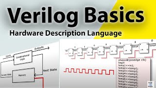
Verilog is a hardware description language (HDL) that shares a syntax similar to the C programming language, making it intuitive for many developers. It is predominantly used in industry for designing FPGAs and simulating digital circuits due to its succinct nature, which often allows for quicker coding compared to its counterpart, VHDL.
Basic Structure
A Verilog program typically comprises several key components:
1. Module: This serves as the fundamental design unit in Verilog, specifying inputs and outputs along with internal circuit behavior. For instance:
- Always Block: This construct specifies behavior that executes continuously as input signals change. Example usage includes:
Data Types and Operators
Verilog supports various data types including wire, reg, integer, real, and time. The language also employs several operators similar to those found in VHDL, with bitwise, arithmetic, and comparison operators.
The section also includes practical examples, such as the implementation of a simple AND gate using the assign statement, showcasing how Verilog allows for straightforward digital circuit implementations.
In summary, understanding Verilog’s structure and capabilities is crucial for effective digital circuit design in modern FPGA applications.
Youtube Videos

Audio Book
Dive deep into the subject with an immersive audiobook experience.
Introduction to Verilog
Chapter 1 of 4
🔒 Unlock Audio Chapter
Sign up and enroll to access the full audio experience
Chapter Content
Verilog is a hardware description language that is similar in syntax to the C programming language. It is widely used in the industry for FPGA design and digital circuit simulation. Verilog is more concise than VHDL, making it easier to write but also somewhat less verbose.
Detailed Explanation
Verilog is a language specifically designed for describing hardware. Its syntax resembles that of C, which is a popular programming language. This makes learning Verilog easier for those who already know C. One key characteristic of Verilog is its conciseness; it allows users to express complex operations with fewer lines of code compared to VHDL. However, this simplicity might come at the cost of some detail, making it slightly less descriptive when writing complex designs.
Examples & Analogies
Think of Verilog as a recipe that uses shorthand instructions. Just like a chef might say 'blend' instead of 'mix the ingredients manually until they reach a smooth consistency', Verilog uses fewer words to convey ideas. This can speed up the cooking process (coding), but it may leave out some finer details you might want when explaining your dish (circuit) to someone else.
Verilog Basic Structure
Chapter 2 of 4
🔒 Unlock Audio Chapter
Sign up and enroll to access the full audio experience
Chapter Content
A Verilog program typically consists of the following elements:
- Module: The module is the basic unit of design in Verilog. It defines the inputs, outputs, and the internal behavior of the circuit.
Example:
module AND_GATE (input A, input B, output Y);
assign Y = A & B;
endmodule
- Always Block: The always block is used to define behavior that executes continuously whenever the input signals change.
Example:
always @ (A or B) begin
Y = A & B;
end
Detailed Explanation
Each Verilog program starts with a 'module', which serves as a blueprint for a specific component of a circuit. The module outlines what inputs and outputs are needed. Following this, the 'always block' is employed when the outputs need to react to changes in the inputs. It specifies actions that should take place whenever the input signals change, thus mimicking the behavior of real electronic components.
Examples & Analogies
Imagine a module as a light switch. It has defined inputs (the position of the switch) and outputs (the light being on or off). The always block, then, is like a response system that instructs the light to turn on or off every time the switch is flipped. Just like how you might react immediately every time you see a light switch change, the always block ensures the circuit responds to input changes without delay.
Verilog Data Types and Operators
Chapter 3 of 4
🔒 Unlock Audio Chapter
Sign up and enroll to access the full audio experience
Chapter Content
● Data Types: Verilog supports wire, reg, integer, real, time, and other types to represent signals and variables.
● Operators: Verilog supports similar operators to VHDL, such as bitwise (&, |), arithmetic (+, -, *), and comparison (==, !=) operators.
Detailed Explanation
In Verilog, different data types are used to represent various forms of data. For example, 'wire' is typically used for connecting different components in a circuit, while 'reg' is used to hold binary values. Besides the data types, operators in Verilog allow manipulation of these data types, enabling arithmetic calculations, logical comparisons, and bitwise operations, just like in standard programming languages.
Examples & Analogies
Think of data types as different containers in a kitchen. A 'wire' is like a string bag, which can carry anything that needs to be transported—it's flexible and connects things. A 'reg' is like a jar, which securely holds ingredients until needed. The operators are your utensils that let you mix or separate the ingredients—whether it's adding them, comparing their sizes, or using a blender to process them.
Example: Simple AND Gate
Chapter 4 of 4
🔒 Unlock Audio Chapter
Sign up and enroll to access the full audio experience
Chapter Content
module AND_GATE (input A, input B, output Y);
assign Y = A & B;
endmodule
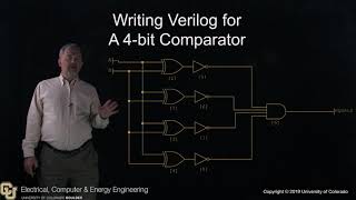
In this Verilog example, the AND_GATE module defines two inputs A and B, and one output Y. The assign statement is used to implement the AND operation between A and B.
Detailed Explanation
The provided example showcases a simple digital circuit called an AND gate. The module here is named 'AND_GATE' and has two inputs (A and B) and one output (Y). The line assign Y = A & B; describes the logical AND operation; it indicates that Y will only be true (or 1) when both A and B are true (or 1). This simple example illustrates how to define a circuit in Verilog and how to perform basic logic operations.
Examples & Analogies
Consider the AND gate like a security system that only allows access when both paired keys (A and B) are presented. If both keys are used together (meaning both inputs are true), access is granted (output Y becomes true). If one or both keys are missing, access is denied, just like how the output remains false. This visual helps in understanding how logical relationships work in circuits.
Key Concepts
-
Verilog: A concise hardware description language crucial for designing FPGAs.
-
Module: The fundamental unit of design that specifies inputs, outputs, and logic in Verilog.
-
Always Block: A structure that defines continuous behavior in response to signal changes.
-
Data Types: Various types including
wireandregused in Verilog. -
Operators: Symbols for performing bitwise, arithmetic, and comparison operations.
Examples & Applications
An example of a simple AND gate in Verilog:
module AND_GATE (input A, input B, output Y);
assign Y = A & B;
endmodule
Using an always block to define AND logic:
always @(A or B) begin
Y = A & B;
end
Memory Aids
Interactive tools to help you remember key concepts
Rhymes
In Verilog, we code with ease, a module here, and data please!
Stories
Imagine Verilog as a chef. The modules are the recipes, guiding you through the process of mixing ingredients (inputs) to create a delicious dish (output).
Memory Tools
Use 'WIRy' to recall the data types: Wire, Integer, Reg.
Acronyms
**CAM** - **C**ircuit **A**ssignment **M**odule
Remember that circuits are assigned values through modules in Verilog.
Flash Cards
Glossary
- Verilog
A hardware description language similar to C, used for FPGA design and digital circuit simulation.
- Module
The basic design unit in Verilog that specifies inputs, outputs, and internal behavior.
- Always Block
A block of code in Verilog that executes continuously when the input signals change.
- Data Types
Various types used in Verilog to represent signals and variables, such as
wireandreg.
- Operators
Symbols used to perform operations on data in Verilog, including bitwise and arithmetic operations.
Reference links
Supplementary resources to enhance your learning experience.