
Lab Work on Precision Rectifiers and Peak Detectors
Interactive Audio Lesson
Listen to a student-teacher conversation explaining the topic in a relatable way.
Precision Rectifiers
🔒 Unlock Audio Lesson
Sign up and enroll to listen to this audio lesson

Today we're discussing precision rectifiers. These circuits use operational amplifiers instead of traditional diodes for rectifying AC signals.

Why do we use op-amps instead of diodes?
Great question! Op-amps can provide much more accurate rectification, particularly at low signal levels where diodes may not conduct properly. Can anyone remind me of the key advantages of precision rectifiers?

They allow for accurate conversion of AC to DC?
Exactly! So, precision rectifiers are crucial in signal conditioning and measuring applications.
Peak Detectors
🔒 Unlock Audio Lesson
Sign up and enroll to listen to this audio lesson

Now let's talk about peak detectors. Who can explain what a peak detector does?

It tracks the highest voltage of a waveform, right?
Correct! They hold the peak voltage for some time, allowing for further processing. Can you think of applications where this would be useful?

I remember using them in audio systems to detect peak levels for sound monitoring.
Exactly! They're also used in oscilloscopes. Let's move on to how to build these circuits.
Lab Procedures
🔒 Unlock Audio Lesson
Sign up and enroll to listen to this audio lesson
For our lab work, we will build both a precision rectifier and a peak detector circuit. First, can anyone list the materials we will need?
We need op-amps, diodes, resistors, capacitors, a signal generator, and an oscilloscope.
Good! In the first step, we will construct the precision rectifier circuit. Can anyone explain how we should observe the output signal?
We should connect the output to the oscilloscope to see the rectified signal.
Exactly! After that, we will build the peak detector and measure the peak value of a sinusoidal input. Remember to compare it to the expected value.
Review and Wrap-Up
🔒 Unlock Audio Lesson
Sign up and enroll to listen to this audio lesson
As we conclude today's session, who can summarize the main points we covered?
We learned about precision rectifiers that enhance AC to DC conversion accuracy, and how peak detectors track maximum signal values.
And we also discussed how we will construct these circuits and analyze their outputs using an oscilloscope.
Great job, everyone! Keep studying these concepts, as they are fundamental in instrumentation and measurement systems.
Introduction & Overview
Read summaries of the section's main ideas at different levels of detail.
Quick Overview
Standard
In this section, students will learn how to construct precision rectifiers and peak detectors, using op-amps and diodes. The exercise involves practical applications of these circuits, enabling accurate signal processing and measurement in instrumentation systems.
Detailed
Lab Work on Precision Rectifiers and Peak Detectors
This section guides students in designing and constructing a precision rectifier and peak detector circuit using operational amplifiers (op-amps).
Overview
Precision rectifiers allow for the accurate rectification of low-level AC signals, overcoming limitations of traditional diode rectifiers. Peak detectors enable the tracking of maximum signal values in various applications, including audio and measurement systems.
Objectives
- Build a precision rectifier circuit and observe how it functions.
- Construct a peak detector circuit to measure the peak voltage of sinusoidal signals.
- Utilize an oscilloscope to compare measured outputs against expected results.
Significance
Understanding these circuits enhances the ability to process and condition signals in instrumentation, improving accuracy in measurements and monitoring tasks.
Youtube Videos


Audio Book
Dive deep into the subject with an immersive audiobook experience.
Lab Objective
Chapter 1 of 5
🔒 Unlock Audio Chapter
Sign up and enroll to access the full audio experience
Chapter Content
● Objective: Build a precision rectifier and peak detector circuit.
Detailed Explanation
The objective of this lab work is to construct two important circuits: a precision rectifier and a peak detector. The precision rectifier is designed to accurately convert an alternating current (AC) signal into a direct current (DC) signal, while the peak detector is used to measure the maximum voltage of a waveform. Both circuits are essential for signal conditioning in instrumentation systems.
Examples & Analogies
Think of the precision rectifier as a sophisticated water valve that controls the flow of water (the signal) more efficiently than a simple flap valve (traditional diode), allowing the water to flow even when the pressure is very low.
Materials Needed
Chapter 2 of 5
🔒 Unlock Audio Chapter
Sign up and enroll to access the full audio experience
Chapter Content
● Materials:
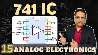
1. Op-Amps (e.g., LM741)
2. Diodes (e.g., 1N4148)
3. Resistors and capacitors
4. Signal generator and oscilloscope
Detailed Explanation
To conduct the lab work, several components are necessary. The Op-Amp, such as the LM741, is the main component used in both circuits. Diodes like the 1N4148 are crucial for the peak detector circuit. Additionally, various resistors and capacitors will be required for the construction of both circuits. A signal generator is used to provide the input signals, and an oscilloscope is used to visualize the output.
Examples & Analogies
Imagine building a small robot: just as you need motors, batteries, wheels, and sensors to construct it, here you need specific electronic components (Op-Amps, diodes, etc.) to create effective circuits.
Procedure for Precision Rectifier
Chapter 3 of 5
🔒 Unlock Audio Chapter
Sign up and enroll to access the full audio experience
Chapter Content
● Procedure:
1. Construct a precision rectifier circuit and observe the rectified output signal.
Detailed Explanation
Start by assembling the precision rectifier circuit according to the circuit diagram provided. Connect the Op-Amp, the diodes, and the necessary resistors. Once the circuit is set up, apply an AC signal using the signal generator. Carefully observe the output signal on the oscilloscope. The output should show a DC signal that corresponds to the absolute value of the input AC signal, indicating successful rectification.
Examples & Analogies
Picture a water wheel that only allows water to flow in one direction; no matter how the water flows, the wheel converts it into continuous forward motion (DC). This is similar to how the precision rectifier takes fluctuating AC signals and converts them into a steady DC output.
Procedure for Peak Detector
Chapter 4 of 5
🔒 Unlock Audio Chapter
Sign up and enroll to access the full audio experience
Chapter Content
- Build a peak detector circuit and measure the peak value of a sinusoidal input signal.
Detailed Explanation
Next, construct the peak detector circuit. This circuit will typically involve an Op-Amp and a diode. Connect the components as per the schematic. After building the circuit, use the signal generator to input a sinusoidal waveform. The peak detector will capture and hold the maximum voltage level of that waveform. You can measure this peak value with the oscilloscope and verify that it matches the input signal's maximum value.
Examples & Analogies
Think of the peak detector as a sponge that soaks up water (the peak voltage) when a wave passes by. Once the water is absorbed, the sponge retains the maximum amount until squeezed or emptied; similarly, the peak detector 'captures' the highest voltage of the input signal.
Comparing Peak Values
Chapter 5 of 5
🔒 Unlock Audio Chapter
Sign up and enroll to access the full audio experience
Chapter Content
- Use the oscilloscope to compare the measured peak with the expected value.
Detailed Explanation
Finally, use the oscilloscope to analyze the output from the peak detector. Compare the measured peak voltage displayed on the oscilloscope with the theoretical peak value that should occur with the given sinusoidal input. This comparison helps students understand the accuracy of their circuit design and the effectiveness of the peak detector.
Examples & Analogies
Imagine a target shooting range: measuring the bullet's accuracy against a target helps evaluate the marksman's skill. In electronics, checking the measured peak against the expected value assesses how well the circuit performs.
Key Concepts
-
Precision Rectifier: An op-amp-based circuit that provides accurate rectification of low-level AC signals.
-
Peak Detector: A circuit that tracks and holds the maximum voltage of a waveform for processing.
Examples & Applications
An example of a precision rectifier application is in audio systems, where low signal levels need to be accurately converted from AC to DC.
In an oscilloscope setup, a peak detector can be used to measure and display the maximum signal levels in real-time.
Memory Aids
Interactive tools to help you remember key concepts
Rhymes
When your signal’s low and needs a boost, use a rectifier for the proper juice.
Stories
Imagine a concert where the highest note needs to be remembered. Our peak detector listens carefully, capturing that sweet note and holding it just for you.
Memory Tools
Remember: 'P-Power R-Rectifier' to think about the precision rectifier’s role.
Acronyms
PDP
Precision (rectifier)
Detector (peak)
Processing (signals).
Flash Cards
Glossary
- Precision Rectifier
An op-amp-based circuit that accurately rectifies an AC signal without traditional diodes.
- Peak Detector
A circuit that tracks and holds the peak voltage of a waveform for further processing.
- Operational Amplifier (OpAmp)
A versatile electronic component used for signal amplification and processing.
- Signal Conditioning
The process of manipulating an input signal in order to prepare it for processing.
Reference links
Supplementary resources to enhance your learning experience.