
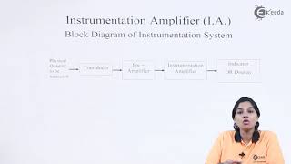
Basic Design of Instrumentation Amplifiers
Interactive Audio Lesson
Listen to a student-teacher conversation explaining the topic in a relatable way.
Configuration of Instrumentation Amplifiers
🔒 Unlock Audio Lesson
Sign up and enroll to listen to this audio lesson

Today, we're going to talk about the configuration of instrumentation amplifiers. Can anyone tell me how many op-amps are typically used in such a circuit?

Is it three op-amps?
Correct! We use three op-amps. The first two are configured to handle the input signals while the third amplifies the output. This arrangement allows us to reject noise effectively. Can anyone explain why this configuration is important?

It’s important because it improves the accuracy of low-level signals, right?
Exactly. The differential configuration helps isolate the signal of interest from the noise. It's essential for sensitive applications like medical instrumentation.

What type of signals are we looking at typically?
Good question! We're typically looking at low-level signals from sensors and transducers.

Can these amplify both input signals effectively?
Yes, they amplify the difference between the signals while rejecting common-mode components. Let's summarize what we've learned today.
We've established that an instrumentation amplifier consists of three op-amps in a configuration designed for precision signal amplification, focusing specifically on high input impedance and noise rejection.
Gain Equation
🔒 Unlock Audio Lesson
Sign up and enroll to listen to this audio lesson

Now let's move on to the gain equation for instrumentation amplifiers. Can anyone give me the formula?
Is it A_v equals R_f over R_gain?
Great! What do the terms R_f and R_gain represent?
R_f is the feedback resistor, and R_gain sets the overall gain, right?
Exactly! High input impedance and the careful choice of these resistors help in amplifying weak signals without burdening signal sources. Why do you think a high input impedance is essential?
It prevents loading the sensor; otherwise, we might get inaccurate readings.
That’s right! Taking that concept further, can you think of where we might apply these amplifiers in real life?
They’re used in medical devices, like ECG machines!
Perfect! To recap, today we covered the gain of instrumentation amplifiers and how crucial the values of R_f and R_gain are in determining the amplifier's performance.
Introduction & Overview
Read summaries of the section's main ideas at different levels of detail.
Quick Overview
Standard
The section details the configuration and gain equation of instrumentation amplifiers, explaining how they utilize three op-amps to achieve high input impedance and a superior common-mode rejection ratio (CMRR). This makes them particularly useful for applications involving low-level signals and sensors.
Detailed
Detailed Summary
Instrumentation amplifiers are specialized circuits designed for the amplification of low-level signals, making them essential in various measurement and control applications. They typically consist of three operational amplifiers (op-amps): two at the input configured in a differential manner, and one at the output that boosts the signal. This design inherently rejects common-mode noise, allowing them to amplify only the difference between two input signals.
Configuration
- Three Op-Amps: The circuit usually employs two op-amps at the front end for signal processing and one for overall gain amplification. The configuration is specifically tailored to operate in a differential mode, which filters out common-mode noise that can interfere with the intended signal.
Gain Equation
- The gain (
A_v
) of the instrumentation amplifier can be calculated using the equation:
A_v = R_f / R_{gain}
Where:
- R_f is the feedback resistor.
- R_{gain} is a resistor that sets the gain of the amplifier.
This design enables high input impedance along with low output impedance, essentially allowing the amplifier to interface seamlessly with low-level signal sources, such as sensors. The instrumentation amplifier’s ability to effectively reject noise and amplify only the intended signals makes it invaluable in medical instruments, industrial sensors, and precision measurement systems.
Youtube Videos

Audio Book
Dive deep into the subject with an immersive audiobook experience.
Configuration of Instrumentation Amplifiers
Chapter 1 of 2
🔒 Unlock Audio Chapter
Sign up and enroll to access the full audio experience
Chapter Content
● Configuration:
○ An instrumentation amplifier typically consists of three Op-Amps: two in the front end for signal conditioning and one for output amplification.
○ The front-end Op-Amps are connected in a differential configuration to reject common-mode noise and amplify the difference between the two input signals.
Detailed Explanation
Instrumentation amplifiers are designed using three operational amplifiers (Op-Amps). In this configuration, there are two Op-Amps at the front designed to condition the incoming signals. They help to filter out unwanted noise that can affect the signal quality. The third Op-Amp is responsible for amplifying the output from the first two. By employing this arrangement, the amplifier can effectively enhance the audio signal's integrity while eliminating common-mode noise (interference that affects both inputs the same way).
Examples & Analogies
Imagine you're trying to listen to a friend speaking while there's loud music playing in the background. The two front-end Op-Amps are like two friends who can hear each other well, filtering out the distracting music. They focus on the conversation (the important signal), and then they pass on that clear conversation to the third friend, who amplifies it.
Gain Equation of Instrumentation Amplifiers
Chapter 2 of 2
🔒 Unlock Audio Chapter
Sign up and enroll to access the full audio experience
Chapter Content
● Gain Equation:
○ The gain of an instrumentation amplifier is given by:
● Av=RfRgainA_v = \frac{R_f}{R_{gain}}
Where:
○ R_f is the feedback resistor,
○ R_{gain} is the resistor that sets the gain.
Detailed Explanation
The gain of an instrumentation amplifier, which determines how much the input signal will be amplified, is calculated using a specific equation. In this equation, R_f represents the feedback resistor that connects to the output and helps determine how the amplifier behaves. R_gain is another resistor that directly influences the amount of gain. Essentially, by selecting the right values for these resistors, an engineer can control how much amplification the instrumentation amplifier will provide to the input signal.
Examples & Analogies
Think of the gain of an instrumentation amplifier like the volume on a speaker. Just as you can turn the volume up or down by adjusting the knob (akin to changing the resistor values), you can control how loud the sound (input signal) becomes. By adjusting the resistors, you can make the sound softer or louder to suit the environment, just like you would set the desired gain for your audio signals.
Key Concepts
-
Instrumentation Amplifier: A specialized amplifier for low-level signal amplification.
-
Op-Amps in Configuration: Three op-amps are used in the instrumentation amplifier for differential input handling.
-
Common-Mode Rejection Ratio: This enables the amplifier to reject noise effectively.
-
Gain Equation: The relationship between R_f and R_gain determines the amplifier's output.
Examples & Applications
Using an instrumentation amplifier for ECG signal amplification in medical devices.
Employing instrumentation amplifiers in strain gauge applications for precise measurements.
Memory Aids
Interactive tools to help you remember key concepts
Rhymes
Three op-amps at play, amplify signals away, with R_f and R_gain, clear noise in our way.
Stories
Imagine a doctor needing clear signals from a patient's weak heartbeat. Using three op-amps, the information is amplified beautifully, filtering out the noise, just like a hero saving the day in the medical world.
Memory Tools
To remember the components of instrumentation amplifiers: 'O-N-E' - One output and No common noise Equals clarity.
Acronyms
C.M.R.R
'Cool Machines Reject Riffraff' - illustrating that common-mode rejection keeps the essential signals clear.
Flash Cards
Glossary
- Instrumentation Amplifier
A type of differential amplifier designed for low-level signal amplification with high input impedance.
- Operational Amplifier (OpAmp)
A high-gain electronic voltage amplifier with differential inputs and a single-ended output.
- CommonMode Rejection Ratio (CMRR)
The ability of a circuit to reject common-mode signals, such as noise.
- Gain
The ratio of output signal to input signal in an amplifier.
- Feedback Resistor (R_f)
A resistor used in feedback loops within amplifiers to control the gain.
- Gain Resistor (R_gain)
A resistor that sets the gain of the instrumentation amplifier.
Reference links
Supplementary resources to enhance your learning experience.