
Op-Amps in Instrumentation Circuits
Interactive Audio Lesson
Listen to a student-teacher conversation explaining the topic in a relatable way.
Introduction to Instrumentation Circuits
🔒 Unlock Audio Lesson
Sign up and enroll to listen to this audio lesson

Today, we're diving into instrumentation circuits. Can anyone tell me why we need these circuits?

Aren't they used to amplify signals from sensors?
Exactly! Instrumentation circuits are crucial for amplifying and processing signals from sensors. They are especially important when we need accurate signal conditioning in measurement systems.

What makes operational amplifiers the best choice for these circuits?
Great question! Op-Amps provide high gain, precision, and versatility, which are essential for effective signal conditioning.

Is that why we see them a lot in medical instruments?
Absolutely! They help us get precise readings in sensitive environments like medical settings.
Instrumentation Amplifiers
🔒 Unlock Audio Lesson
Sign up and enroll to listen to this audio lesson

Now, let's discuss instrumentation amplifiers in detail. They typically use three Op-Amps. Who can describe their configuration?

I think the two Op-Amps at the front are for signal conditioning, right?
Correct! They are arranged in a differential configuration to reject noise and amplify the difference between inputs. Can anyone explain why high input impedance is important in these amplifiers?
It prevents loading the sensor, especially for high-impedance sources.
Exactly! And this characteristic helps in many applications, from medical to industrial sensors.
Precision Rectifiers and Peak Detectors
🔒 Unlock Audio Lesson
Sign up and enroll to listen to this audio lesson
Who can explain what a precision rectifier does?
It rectifies AC signals without traditional diodes, allowing for accurate rectification at low signal levels.
Good! This capability is crucial for signal conditioning. What about peak detectors?
They track and hold the peak voltage, useful for measuring maximum signal levels.
Correct! Peak detection is significant in audio systems and communication applications.
Low-Noise Amplifiers
🔒 Unlock Audio Lesson
Sign up and enroll to listen to this audio lesson
Let’s move to low-noise amplifiers. Why do you think they are critical in RF systems?
They need to amplify weak signals while adding minimal noise!
Exactly! Choosing the right low-noise Op-Amp is essential. Can anyone name a factor that’s important in designing these amplifiers?
Impedance matching and bandwidth are key considerations.
Well done! These considerations ensure optimal performance.
Differential Amplifiers
🔒 Unlock Audio Lesson
Sign up and enroll to listen to this audio lesson
Differential amplifiers play a crucial role in instrumentation. Can anyone explain their key characteristic?
They amplify the difference between two input signals and reject common-mode noise.
Correct! This makes them ideal for precision applications. What’s the formula we use for their gain?
It’s Av=Rf/Rin=R2/R1.
Great! Understanding these fundamentals is key to working in fields like sensor technology and control systems.
Introduction & Overview
Read summaries of the section's main ideas at different levels of detail.
Quick Overview
Standard
The section elaborates on instrumentation amplifiers, precision rectifiers, peak detectors, low-noise amplifiers, and differential amplifiers, detailing their designs, characteristics, and applications in various measurement and control systems.
Detailed
Op-Amps in Instrumentation Circuits
Instrumentation circuits are essential for amplifying and processing low-level signals from sensors. This section explores the diverse applications of operational amplifiers (Op-Amps) in these circuits, including:
Instrumentation Amplifiers
Instrumentation amplifiers are specialized amplifiers designed for high input impedance and low-level signal amplification. They typically consist of three Op-Amps and offer excellent common-mode rejection, making them ideal for medical instruments and industrial sensors.
- Gain Equation: The gain of an instrumentation amplifier can be expressed as Av=Rf/Rgain, highlighting the relationship between feedback and gain-setting resistors.
Precision Rectifiers and Peak Detectors
These circuits convert AC signals to DC and measure peak values, enhancing signal processing capabilities for applications in audio systems and oscilloscopes.
Low-Noise Amplifiers (LNAs)
LNAs are vital for amplifying weak signals with minimal noise, particularly in RF systems and medical instruments, emphasizing low noise and impedance matching in design considerations.
Differential Amplifiers
Differential amplifiers, with their ability to focus on the difference between two input signals while rejecting noise, are crucial in instrumentation.
The section concludes by discussing lab activities that provide hands-on experience in building and testing these circuits, reinforcing the theoretical concepts covered.
Youtube Videos
Audio Book
Dive deep into the subject with an immersive audiobook experience.
Introduction to Instrumentation Circuits
Chapter 1 of 6
🔒 Unlock Audio Chapter
Sign up and enroll to access the full audio experience
Chapter Content
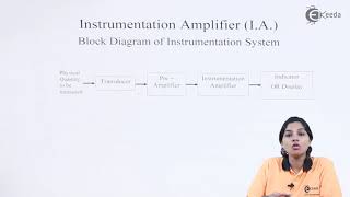
Instrumentation circuits are specialized circuits used to amplify and process signals from sensors or transducers. These circuits play a vital role in measurement and control systems, where accurate signal conditioning is crucial. Operational amplifiers (Op-Amps) are extensively used in instrumentation circuits due to their high gain, precision, and versatility. This chapter focuses on the application of Op-Amps in instrumentation circuits, exploring their design and analysis, and highlighting how they can be used to improve accuracy and performance in various measurement systems.
Detailed Explanation
Instrumentation circuits are tailored specifically to enhance signals coming from sensors or transducers, which are devices that convert physical parameters like temperature or pressure into electrical signals. When these signals are very weak, instrumentation circuits amplify them to make them usable in measurement and control applications. Operational amplifiers, or Op-Amps, are key components in these circuits due to their ability to amplify signals significantly while maintaining high precision. In this chapter, we will delve into how Op-Amps are integrated into these circuits and how their design and functionality contribute to improving the accuracy and performance in various applications, such as measuring temperature or pressure.
Examples & Analogies
Imagine a quiet sound in a very noisy room. The sound represents a weak signal from a sensor, while the background noise represents interference or unwanted signals. Instrumentation circuits can be compared to a powerful microphone that picks up the quiet sound clearly while helping to drown out the surrounding noise, allowing us to hear the important information without being distracted.
Instrumentation Amplifiers
Chapter 2 of 6
🔒 Unlock Audio Chapter
Sign up and enroll to access the full audio experience
Chapter Content
An instrumentation amplifier is a type of differential amplifier designed specifically for low-level signal amplification, offering high input impedance and excellent common-mode rejection ratio (CMRR). These characteristics make instrumentation amplifiers ideal for use with sensors and other low-level signal sources.
Detailed Explanation
Instrumentation amplifiers are specialized types of differential amplifiers that focus on amplifying weak signals. They have unique properties such as high input impedance, which prevents them from affecting the signals they are measuring, and a high common-mode rejection ratio (CMRR), which means they can effectively filter out noise or interference present on both input lines. This makes them particularly suitable for applications where precise measurement of small signals is critical, such as in medical instruments where tiny bio-signals need to be accurately amplified.
Examples & Analogies
Think of an instrumentation amplifier as a sensitive microphone tailored to pick up soft voices in a crowded room. It's designed to focus on and amplify one person’s voice while ignoring background chatter or other noise, ensuring the message is conveyed clearly without distortion.
Basic Design of Instrumentation Amplifiers
Chapter 3 of 6
🔒 Unlock Audio Chapter
Sign up and enroll to access the full audio experience
Chapter Content
● Configuration:
- An instrumentation amplifier typically consists of three Op-Amps: two in the front end for signal conditioning and one for output amplification.
- The front-end Op-Amps are connected in a differential configuration to reject common-mode noise and amplify the difference between the two input signals.
● Gain Equation:
- The gain of an instrumentation amplifier is given by:
Av=RfRgainA_v = \\frac{R_f}{R_{gain}}
Where:
- R_f is the feedback resistor,
- R_{gain} is the resistor that sets the gain.
Detailed Explanation
The basic design of an instrumentation amplifier uses three operational amplifiers (Op-Amps). The first two Op-Amps work together in a differential configuration, amplifying the difference between two input signals while cancelling out any common-mode noise that might affect both inputs equally. The third Op-Amp is used for further amplification, making the output signal even stronger. The gain, or how much the signal is amplified, can be controlled by adjusting a feedback resistor and another resistor that determines the gain value, ensuring versatility in application.
Examples & Analogies
Imagine you have two friends speaking at a low volume at a loud party. You can adjust the volume on your digital recorder to focus specifically on their conversation while lowering the noise from the party. The Op-Amps in an instrumentation amplifier act like that digital recorder, consistently tuning in to the right signals while ignoring everything else.
Key Characteristics of Instrumentation Amplifiers
Chapter 4 of 6
🔒 Unlock Audio Chapter
Sign up and enroll to access the full audio experience
Chapter Content
● High Input Impedance: Ensures that the amplifier does not load the sensor or signal source, which is important for high-impedance sources.
● Low Output Impedance: Makes it easier to interface with other circuits without significant loss of signal.
● High CMRR: Ability to reject common-mode signals (e.g., noise) that affect both input terminals equally.
Detailed Explanation
Instrumentation amplifiers are characterized by three substantial features: high input impedance, low output impedance, and high common-mode rejection ratio (CMRR). High input impedance means that when connected to sensor outputs, the amplifier does not disturb the source signal; it draws very little current. Low output impedance improves the transfer of the output signal to subsequent circuits without substantial loss or distortion. Lastly, high CMRR indicates the amplifier's ability to effectively eliminate noise signals that may be present on both inputs, ensuring a clear output.
Examples & Analogies
Consider a sophisticated ear doctor who has highly sensitive equipment like high-quality headphones (high input impedance) that can read soft sounds without amplifying useless noise. When he tests the patients' hearing (low output impedance), he can accurately relay the results to a loudspeaker system without losing valuable sound quality (high CMRR).
Applications of Instrumentation Amplifiers
Chapter 5 of 6
🔒 Unlock Audio Chapter
Sign up and enroll to access the full audio experience
Chapter Content
● Medical Instruments: Used in electrocardiogram (ECG), electroencephalogram (EEG), and other bio-potential measurements.
● Industrial Sensors: Amplifies signals from temperature sensors, strain gauges, and pressure sensors.
● Precision Measurement: Used in high-accuracy measurement systems where low-level signal amplification is required.
Detailed Explanation
Instrumentation amplifiers are prevalent in multiple applications due to their ability to accurately amplify weak signals. They are found in medical devices like ECG and EEG machines, where they help measure bio-potentials, translating tiny electrical signals from the body into readable data. In industrial settings, they amplify the output from sensors that monitor temperature, pressure, and strain. Finally, they play a critical role in precision measurement systems where accurate signal amplification is paramount to ensure reliability in readings.
Examples & Analogies
Imagine you are in a hospital where doctors are monitoring heart signals using an ECG machine. The instrumentation amplifier inside that machine whispers and amplifies the weak signals generated by the heart into clear beeping sounds that everyone can understand, enabling timely medical decisions.
Lab Work on Instrumentation Amplifiers
Chapter 6 of 6
🔒 Unlock Audio Chapter
Sign up and enroll to access the full audio experience
Chapter Content
● Objective: Build an instrumentation amplifier and measure its output.
● Materials:
1. Op-Amps (e.g., INA128 or LM741)
2. Resistors (e.g., 10 kΩ)
3. Signal generator and oscilloscope
● Procedure:
1. Construct the instrumentation amplifier using three Op-Amps and resistors.
2. Apply a differential input signal to the amplifier and measure the output.
3. Verify the gain by comparing the measured output with the input signal.
Detailed Explanation
The lab exercise involves building your own instrumentation amplifier to see its real-world applications. You will gather specified components, including the Op-Amps and resistors, and create a circuit according to the design principles discussed. By applying a known differential input signal, you will then measure the output using an oscilloscope. Finally, you will validate the amplifier's gain by comparing the amplified output to the original input, ensuring that the design works as expected.
Examples & Analogies
Think of this lab work as cooking your favorite dish. You gather all your ingredients (Op-Amps and resistors) and carefully follow a recipe (the circuit design) to create a magnificent meal (the amplification of your signal). At the end of cooking, you taste the dish (measuring the output) to check if it matches what you anticipated, confirming that your cooking was successful.
Key Concepts
-
Instrumentation Amplifiers: Specialized amplifiers designed for high input impedance and low-level signal amplification.
-
Common-Mode Rejection Ratio (CMRR): A measure of how well an amplifier can reject common-mode signals.
-
Precision Rectifiers: Circuits that rectify AC signals accurately using Op-Amps.
-
Low-Noise Amplifiers: Amplifiers that minimize added noise while amplifying weak signals.
-
Differential Amplifiers: Amplifiers that focus on the difference between two input signals.
Examples & Applications
Measurement of electrocardiogram (ECG) signals using instrumentation amplifiers for enhanced precision.
Using precision rectifiers in audio systems to convert sound signals for processing.
Low-noise amplifiers amplifying small bio-potential signals from medical sensors.
Memory Aids
Interactive tools to help you remember key concepts
Rhymes
Op-Amps are precise, they never tell lies, amplifying signals, they’re the smart guys.
Stories
Imagine a doctor using instruments that amplify body signals, ensuring accuracy just like how Op-Amps ensure clarity in circuitry.
Memory Tools
Remember the acronym 'CLAP' for key amplifier types: C for Common-mode rejection, L for Low-noise amplifier, A for Amplifier (Instrumentation), and P for Precision Rectifier.
Acronyms
To recall the key functions of Op-Amps, remember 'SCRIBE'
for Signal processing
for Conditioning
for Rectification
for Input handling
for Bandwidth control
for Error reduction.
Flash Cards
Glossary
- Instrumentation Circuit
Specialized circuits used to amplify and process signals from sensors.
- OpAmp
Operational amplifier, a versatile electronic component used for signal processing.
- Instrumentation Amplifier
A type of differential amplifier optimized for high input impedance and low-level signal amplification.
- CommonMode Rejection Ratio (CMRR)
A measure of the ability of an amplifier to reject common-mode signals.
- Precision Rectifier
A circuit that rectifies AC signals using Op-Amps for accurate signal processing.
- Peak Detector
A circuit that captures and holds the peak voltage of an input signal.
- LowNoise Amplifier (LNA)
An amplifier designed to amplify weak signals with minimal added noise.
- Differential Amplifier
An amplifier that amplifies the difference between two input voltages while rejecting common-mode noise.
- Signal Conditioning
The process of modifying a signal to make it suitable for processing.
- Gain
The ratio of output signal to input signal in an amplifier.
Reference links
Supplementary resources to enhance your learning experience.