
Instrumentation Amplifiers
Interactive Audio Lesson
Listen to a student-teacher conversation explaining the topic in a relatable way.
Introduction to Instrumentation Amplifiers
🔒 Unlock Audio Lesson
Sign up and enroll to listen to this audio lesson

Today, we will explore instrumentation amplifiers, which are integral for low-level signal amplification in sensor applications. Can anyone tell me why high input impedance is essential in these amplifiers?

Isn't it to avoid loading the sensor?
Exactly! High input impedance allows the amplifier to interface without affecting the sensor's output. Now, can someone define common-mode noise?

Common-mode noise affects both inputs equally, right?
Correct! Instrumentation amplifiers are designed to reject this noise while amplifying differential signals.
To help remember this, you can think of the acronym CMRR, which stands for Common-Mode Rejection Ratio!

What's the relationship of Rf to the gain?
Great question! The gain is calculated as $ A_v = \frac{R_f}{R_{gain}} $, where Rf is the feedback resistor. Always remember the formula!
Key Characteristics and Applications
🔒 Unlock Audio Lesson
Sign up and enroll to listen to this audio lesson

Let’s talk about the key characteristics of instrumentation amplifiers. Can anyone name the three main characteristics?

High input impedance, low output impedance, and high CMRR?
Excellent! Now, why do you think a low output impedance is critical?
It helps in better interfacing with other circuits, reducing signal loss?
Precisely! Low output impedance simplifies connections. Next, let’s discuss applications. Who can give me an example of where we use instrumentation amplifiers?
In medical devices like ECG machines!
Right again! Instrumentation amplifiers are indeed critical in bio-potential measurements due to their precision.
Lab Work on Instrumentation Amplifiers
🔒 Unlock Audio Lesson
Sign up and enroll to listen to this audio lesson
Now it’s time for some hands-on experience! What materials do we need to build an instrumentation amplifier?
We'll need Op-Amps, resistors, a signal generator, and an oscilloscope.
Correct! The goal is to build the amplifier and measure its output. What is the first step?
Construct the amplifier circuit with the Op-Amps and resistors.
Exactly! Following that, apply a differential input signal. Why is it important to verify the gain?
To ensure our amplifier works correctly and matches the expected output!
Great observation! Let's make sure we document our results for comparison.
Introduction & Overview
Read summaries of the section's main ideas at different levels of detail.
Quick Overview
Standard
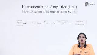
This section covers the design, key characteristics, applications, and laboratory work involved with instrumentation amplifiers. It details how these amplifiers utilize operational amplifiers to ensure precise signal amplification while minimizing noise effects, making them ideal for medical instruments and industrial sensors.
Detailed
Instrumentation Amplifiers
Instrumentation amplifiers are critical components in the realm of signal processing, especially for applications involving low-level signals from sensors or transducers. These amplifiers are designed to amplify the difference between two input signals while rejecting common-mode noise, showcasing high input impedance and low output impedance.
Basic Design of Instrumentation Amplifiers
An instrumentation amplifier typically comprises three operational amplifiers: two configured as differential amplifiers handling the input signals and one for output amplification. The gain of the amplifier can be calculated using the formula:
$$ A_v = \frac{R_f}{R_{gain}} $$
Where $R_f$ represents the feedback resistor, and $R_{gain}$ determines the overall gain. This design is crucial for maintaining accuracy while dealing with sensitive measurements.
Key Characteristics of Instrumentation Amplifiers
- High Input Impedance: Prevents loading the signal source.
- Low Output Impedance: Facilitates easier interfacing with other circuits.
- High CMRR: Enhances the ability to reject noise affecting both inputs equally.
Applications of Instrumentation Amplifiers
Instrumentation amplifiers find their applications in numerous fields:
- Medical Instruments: Utilized in ECG, EEG, and other bio-potential measurements.
- Industrial Sensors: Amplifying signals from devices like temperature sensors.
- Precision Measurement: Integral in high-accuracy systems needing low-level signal amplification.
Lab Work on Instrumentation Amplifiers
Students will engage in hands-on experience by constructing an instrumentation amplifier using components like Op-Amps, resistors, and oscilloscopes to learn through practical application about gain verification and output measurement.
Youtube Videos


Audio Book
Dive deep into the subject with an immersive audiobook experience.
Definition of Instrumentation Amplifiers
Chapter 1 of 5
🔒 Unlock Audio Chapter
Sign up and enroll to access the full audio experience
Chapter Content
An instrumentation amplifier is a type of differential amplifier designed specifically for low-level signal amplification, offering high input impedance and excellent common-mode rejection ratio (CMRR). These characteristics make instrumentation amplifiers ideal for use with sensors and other low-level signal sources.
Detailed Explanation
An instrumentation amplifier is a specialized amplifier that enhances very small signals while minimizing noise. Its high input impedance means it draws little to no current from the sensors, preventing any alteration in the signal being measured. The common-mode rejection ratio (CMRR) indicates how well the amplifier can ignore noise that affects both input signals equally, which is crucial for accurate measurements.
Examples & Analogies
Think of an instrumentation amplifier like a high-quality pair of headphones that amplify sounds without any distortion. Just as good headphones can make a soft spoken word clearer without picking up background noise, an instrumentation amplifier clarifies tiny signals from sensors while ignoring unwanted noise.
Basic Design of Instrumentation Amplifiers
Chapter 2 of 5
🔒 Unlock Audio Chapter
Sign up and enroll to access the full audio experience
Chapter Content
● Configuration:
○ An instrumentation amplifier typically consists of three Op-Amps: two in the front end for signal conditioning and one for output amplification.
○ The front-end Op-Amps are connected in a differential configuration to reject common-mode noise and amplify the difference between the two input signals.
● Gain Equation:
○ The gain of an instrumentation amplifier is given by:
● Av=RfRgainA_v = \frac{R_f}{R_{gain}}
Where:
○ R_f is the feedback resistor,
○ R_{gain} is the resistor that sets the gain.
Detailed Explanation
The basic design of an instrumentation amplifier involves three operational amplifiers (Op-Amps). The first two Op-Amps work together to prepare the signal, ensuring that any interference or noise does not affect the measurement. The third Op-Amp amplifies the processed signal. The gain equation, which determines how much the signal is amplified, depends on a feedback resistor (R_f) and a gain-setting resistor (R_gain). This configuration allows for precise control over the amount of amplification applied to the input signal.
Examples & Analogies
Imagine a relay team in a race. The first two runners pass the baton while avoiding hurdles (noise), ensuring that the last runner receives only the baton (the desired signal) to sprint ahead and finish the race (output amplification) effectively. The gain equation is like the strategy they use to maximize their speed without slowing down due to too many hurdles.
Key Characteristics of Instrumentation Amplifiers
Chapter 3 of 5
🔒 Unlock Audio Chapter
Sign up and enroll to access the full audio experience
Chapter Content
● High Input Impedance: Ensures that the amplifier does not load the sensor or signal source, which is important for high-impedance sources.
● Low Output Impedance: Makes it easier to interface with other circuits without significant loss of signal.
● High CMRR: Ability to reject common-mode signals (e.g., noise) that affect both input terminals equally.
Detailed Explanation
Instrumentation amplifiers possess several key characteristics that make them highly effective for their intended applications. High input impedance prevents them from affecting the signal source, ensuring accurate readings without loading the source down. Low output impedance allows for easier connectivity with subsequent circuits, minimizing signal losses. High CMRR is critical for maintaining signal integrity by rejecting noise that could distort the measurement.
Examples & Analogies
Consider a professional chef (the instrumentation amplifier) who needs to prepare a delicate dish (the measurement). The chef works in a quiet kitchen with high-quality tools (high input impedance) that do not disturb the ingredients (the signal source). Moreover, the chef presents the dish on a sturdy plate (low output impedance) that doesn’t allow any spillage when passing it to the diners. Meanwhile, the chef manages distractions (high CMRR) effectively to maintain focus.
Applications of Instrumentation Amplifiers
Chapter 4 of 5
🔒 Unlock Audio Chapter
Sign up and enroll to access the full audio experience
Chapter Content
● Medical Instruments: Used in electrocardiogram (ECG), electroencephalogram (EEG), and other bio-potential measurements.
● Industrial Sensors: Amplifies signals from temperature sensors, strain gauges, and pressure sensors.
● Precision Measurement: Used in high-accuracy measurement systems where low-level signal amplification is required.
Detailed Explanation
Instrumentation amplifiers are widely used in various fields due to their ability to amplify tiny signals accurately. In medicine, they are pivotal in devices monitoring bio-signals, such as ECGs and EEGs, where precision is crucial. In industrial settings, they boost weak signals from various sensors, improving the accuracy of measurements pertaining to temperature, strain, and pressure. Furthermore, in high-precision measurement applications, they are essential for ensuring that even the slightest changes in readings are detected.
Examples & Analogies
Think of instrumentation amplifiers as skilled artisans in a workshop. Just as an artisan requires precise tools to create detailed work, medical instruments and industrial sensors leverage instrumentation amplifiers to ensure even the smallest detail – like your heartbeat or strain on a machine – is captured accurately for further analysis.
Lab Work on Instrumentation Amplifiers
Chapter 5 of 5
🔒 Unlock Audio Chapter
Sign up and enroll to access the full audio experience
Chapter Content
● Objective: Build an instrumentation amplifier and measure its output.
● Materials:
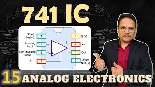
1. Op-Amps (e.g., INA128 or LM741)
2. Resistors (e.g., 10 kΩ)
3. Signal generator and oscilloscope
● Procedure:
1. Construct the instrumentation amplifier using three Op-Amps and resistors.
2. Apply a differential input signal to the amplifier and measure the output.
3. Verify the gain by comparing the measured output with the input signal.
Detailed Explanation
The lab work on instrumentation amplifiers involves a practical approach to reinforcing the theoretical knowledge. The objective is to construct an instrumentation amplifier circuit using three Op-Amps, following the provided schematic. Students then apply a differential input signal and measure the resulting output using an oscilloscope. Finally, they compare the output signal to the input signal to ensure the amplifier is functioning correctly and calculate the gain to confirm it aligns with expectations.
Examples & Analogies
Building an instrumentation amplifier in the lab is akin to cooking a recipe. First, you gather all the ingredients (materials) needed. Then, you follow the steps (procedure) meticulously to create your dish (the amplifier circuit). Once the cooking is done, you taste (measure the output) to verify if it turned out as expected (calculate the gain), adjusting the seasoning (amplifier configuration) if necessary.
Key Concepts
-
Instrumentation Amplifier: A differential amplifier designed for low-level signal amplification.
-
High Input Impedance: Prevents loading the sensor.
-
High CMRR: Ability to reject common-mode signals from affecting the differential signal.
-
Gain Equation: $ A_v = \frac{R_f}{R_{gain}} $.
-
Applications: Used in medical instruments, industrial sensors, and precision measurement systems.
Examples & Applications
In an electrocardiogram (ECG), an instrumentation amplifier amplifies the tiny electrical signals generated by heart activity.
In a temperature monitoring system, an instrumentation amplifier enhances signals from thermocouples to enable accurate readings.
Memory Aids
Interactive tools to help you remember key concepts
Rhymes
Instruments are here to aid, amplifying signals without being weighed.
Stories
Imagine a doctor checking your heartbeat. The instrumentation amplifier acts like your heart's assistant, amplifying the quiet signals from your heart without causing any disturbance.
Memory Tools
Remember 'CHIP': C for CMRR, H for High Impedance, I for Input and P for Precision; qualities of instrumentation amplifiers.
Acronyms
I for Input Impedance, A for Amplification, M for Medical Applications, P for Precision.
Flash Cards
Glossary
- Instrumentation Amplifier
A type of differential amplifier designed for low-level signal amplification, characterized by high input impedance and high common-mode rejection ratio.
- CommonMode Rejection Ratio (CMRR)
A measure of an amplifier's ability to reject common-mode signals, enhancing the differential signal output.
- Gain
The ratio of output voltage to input voltage in an amplifier, often controlled by specific resistors in the circuit.
- Input Impedance
The impedance presented by an amplifier to its input signal, ideally very high in instrumentation amplifiers to avoid loading effects.
- Output Impedance
The impedance seen at the output of an amplifier, ideally low to ensure good signal transfer to other circuits.
Reference links
Supplementary resources to enhance your learning experience.