
Lab Work on Instrumentation Amplifiers
Interactive Audio Lesson
Listen to a student-teacher conversation explaining the topic in a relatable way.
Objective of the Lab
🔒 Unlock Audio Lesson
Sign up and enroll to listen to this audio lesson

Today, we will focus on lab work for creating an instrumentation amplifier. The main objective is to build the circuit and measure how well it amplifies a low-level signal.

What are the benefits of having a differential amplifier in this lab?
Great question! Instrumentation amplifiers reject noise that affects both input terminals equally, enabling precise measurements. This is crucial in sensitive applications.

So, we need to ensure we apply the right input signal to see its effects?
Exactly! By applying a differential input, we can observe how effectively the amplifier works in amplifying the desired signal while rejecting noise.
Remember, the outcome we seek here is reliability and precision in our results.
Materials Required
🔒 Unlock Audio Lesson
Sign up and enroll to listen to this audio lesson

Now, let's break down the materials we will use. We will need Op-Amps like INA128 or LM741.

What makes these Op-Amps suitable for our project?
Good point! They are excellent for low-level signals because they are designed to provide high input impedance and low output impedance, ensuring efficient signal amplification.

And the resistors? How do we determine their value?
The feedback resistor and gain-setting resistor are crucial for defining our amplifier's gain. Using a 10 kΩ resistor, as we'll do today, sets a balanced configuration for our amp.
Let’s make sure we follow the list carefully!
Building and Measuring
🔒 Unlock Audio Lesson
Sign up and enroll to listen to this audio lesson
Now that we have our materials, let's start building. Begin by connecting the Op-Amps as specified.
What should we be aware of when connecting the Op-Amps?
Ensure that the first two Op-Amps are configured in a differential manner—this is vital for noise rejection.
Once we connect everything, what’s next?
Next, we apply our differential signal and use the oscilloscope to measure the output. By comparing it with the input, we can confirm if our gain is as expected.
And how do we verify the gain?
Good question! We verify it by the ratio of output voltage to input voltage. This practice strengthens our understanding of amplifier behavior.
Introduction & Overview
Read summaries of the section's main ideas at different levels of detail.
Quick Overview
Standard
Students will learn to build an instrumentation amplifier using specific materials and procedures, applying a differential input signal and measuring the output to verify the gain.
Detailed
Lab Work on Instrumentation Amplifiers
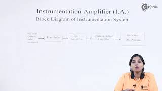
This section outlines the essential hands-on lab activity involved in building an instrumentation amplifier, which is crucial for amplifying low-level signals from various sources.
Objective
The primary objective is to construct an instrumentation amplifier and accurately measure its output, enabling students to gain practical experience in signal amplification using operational amplifiers.
Materials Required
- Op-Amps: Components like INA128 or LM741 are used for their efficiency in handling low-level signals.
- Resistors: Common choices include 10 kΩ resistors, vital for determining the amplifier's gain configuration.
- Signal Generators and Oscilloscopes: These instruments will serve to apply input signals and monitor output results respectively.
Procedure Steps
- Construct the Instrumentation Amplifier: Using three operational amplifiers and resistors to form the necessary differential configuration.
- Apply Differential Input Signal: Input a differential signal through the constructed amplifier.
- Measure and Verify Output: Using the oscilloscope, compare the measured output with the input to confirm the expected gain, solidifying understanding of the amplifier's function in real-world applications.
Youtube Videos
Audio Book
Dive deep into the subject with an immersive audiobook experience.
Objective of the Lab Work
Chapter 1 of 3
🔒 Unlock Audio Chapter
Sign up and enroll to access the full audio experience
Chapter Content
● Objective: Build an instrumentation amplifier and measure its output.
Detailed Explanation
The aim of this lab work is to construct an instrumentation amplifier, which is a specialized type of amplifier that enhances low-level signals. By building this amplifier, students will get hands-on experience, allowing them to understand its functionality and applications in real-world scenarios. The key goal is also to measure the output from the amplifier, which helps in verifying its performance and accuracy.
Examples & Analogies
Think of an instrumentation amplifier like a magnifying glass for sound; just as a magnifying glass makes tiny text easier to read, an instrumentation amplifier makes faint signals easier to measure and analyze.
Materials Needed
Chapter 2 of 3
🔒 Unlock Audio Chapter
Sign up and enroll to access the full audio experience
Chapter Content
● Materials:
1. Op-Amps (e.g., INA128 or LM741)
2. Resistors (e.g., 10 kΩ)
3. Signal generator and oscilloscope
Detailed Explanation
To conduct this lab work, specific components are necessary. The primary component is the Op-Amp, which amplifies the signals. The INA128 and LM741 are common choices due to their reliability and performance in instrumentation applications. Resistors are crucial for setting the gain and ensuring proper operation of the circuits. The signal generator creates the input signals needed to test the amplifier, and the oscilloscope allows for visualization of the output signals on a screen, making it easier to analyze and understand data.
Examples & Analogies
Imagine cooking a dish where each ingredient has a specific role — Op-Amps are your main ingredients, resistors are the spices that adjust flavors, the signal generator is like your oven creating heat, and the oscilloscope is the taste tester that helps you see if you achieved the right flavor.
Procedure for Building the Amplifier
Chapter 3 of 3
🔒 Unlock Audio Chapter
Sign up and enroll to access the full audio experience
Chapter Content
● Procedure:
1. Construct the instrumentation amplifier using three Op-Amps and resistors.
2. Apply a differential input signal to the amplifier and measure the output.
3. Verify the gain by comparing the measured output with the input signal.
Detailed Explanation
The procedure consists of three main steps. First, students will connect the components to build the instrumentation amplifier circuit. It involves configuring the three Op-Amps appropriately with the resistors. Next, a differential input signal is applied, which means the signal is fed in such a way that it can be effectively amplified by the instrumentation amplifier. Finally, students will measure the output using the oscilloscope and compare it with the input signal to calculate the gain, thereby confirming that the amplifier is functioning as intended.
Examples & Analogies
Building this amplifier is like assembling a piece of IKEA furniture: you start with separate pieces (Op-Amps and resistors), follow a clear set of instructions (the circuit design), set it up (constructing the circuit), and at the end, you check to see if it holds together correctly (measuring and verifying the output).
Key Concepts
-
Instrumentation Amplifier: A specialized differential amplifier for low-level signals.
-
Operational Amplifier: A high-gain amplifier used widely in circuits.
-
Gain Formula: The relationship between the output and input voltage of an amplifier.
Examples & Applications
In medical instrumentation, ECG devices use instrumentation amplifiers to detect heart signals accurately.
In industrial settings, these amplifiers enhance readings from strain gauges or temperature sensors.
Memory Aids
Interactive tools to help you remember key concepts
Rhymes
Amplifiers come to play, / Low signals saved the day, / With Op-Amps in the frame, / Noise won't take the gain.
Stories
Imagine a doctor using a sensitive monitor. The instrumentation amplifier captures faint heart signals while filtering out room noise—improving the accuracy of patient care.
Memory Tools
I - Instrumentation, A - Amplifies, D - Differentially: 'IAD' helps to remember the core functions.
Acronyms
RNG
Rf (Feedback resistor)
(Gain resistor)
(Gain calculation) helps remember key parts of gain determination.
Flash Cards
Glossary
- Instrumentation Amplifier
A differential amplifier designed to amplify low-level signals while rejecting noise.
- Gain
The ratio of output voltage to input voltage in an amplifier.
- OpAmp
An operational amplifier, a high-gain electronic voltage amplifier with differential inputs.
- Commonmode Rejection Ratio (CMRR)
A measure of an amplifier's ability to reject input signals common to both input terminals.
- Feedback Resistor
A resistor used in a feedback loop of an amplifier circuit to control gain.
Reference links
Supplementary resources to enhance your learning experience.