
Frequency Response of Filters
Interactive Audio Lesson
Listen to a student-teacher conversation explaining the topic in a relatable way.
Introduction to Frequency Response
🔒 Unlock Audio Lesson
Sign up and enroll to listen to this audio lesson

Today, we'll dive into the frequency response of filters. Can anyone tell me why filters are used in RF systems?

To separate different frequency components from a signal!
Exactly! Filters allow us to manage which frequencies pass through and which do not. This is crucial for signal integrity.

What are the different types of filters?
Great question! We have low-pass filters, high-pass filters, band-pass filters, and band-stop filters. Each serves a different purpose.

Could you explain the cutoff frequency in more detail?
Sure! The cutoff frequency is where the filter starts to attenuate the signal significantly. Let's link this with our memory aid: 'Cut the Frequency at the Source!' to remember its role.

What about the quality factor, Q?
The quality factor indicates how selective a filter is. Higher Q values mean a narrower bandwidth, allowing only specific frequencies. Remember: 'Q for Quality, Sharp and Neat!'
To summarize, filters manage frequency content by using cutoff frequencies and quality factors to define their performance.
Designing Band-Pass Filters
🔒 Unlock Audio Lesson
Sign up and enroll to listen to this audio lesson

Now that we understand the concepts, let’s talk about how to design a band-pass filter. What is the first step in designing a filter?
Choosing the filter type!
Correct! For our task, we determine the range of frequencies we want to allow. For a band-pass filter, we specify the lower and upper cutoff frequencies.
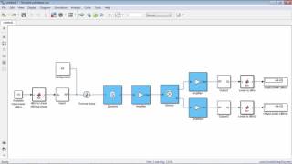
How do we simulate this?
Using simulation tools like SPICE or ADS! After selecting components such as inductors and capacitors, we perform a frequency sweep.
What do we look for in the simulation results?
We evaluate the frequency response, ensuring the filter effectively passes our target frequencies while rejecting others. Remember, 'Assess the Filter, Don’t Let it Falter!'
This sounds hands-on and exciting! What else should we consider?
It's also important to analyze the Q factor to optimize performance. In review, to design filters, we choose type, define cutoff frequencies, simulate, and evaluate performance.
Introduction & Overview
Read summaries of the section's main ideas at different levels of detail.
Quick Overview
Standard
The frequency response of filters is crucial in RF circuit design, where simulations help assess parameters such as cutoff frequencies and quality factors. Understanding how different filter types function ensures optimal performance in signal management.
Detailed
Frequency Response of Filters
Filters play a vital role in RF and HF circuit design by controlling the frequency components of signals. The frequency response of filters allows engineers to determine which frequencies to pass and which to reject. This section elaborates on the significance of filters, detailing the different types (low-pass, high-pass, band-pass, and band-stop) and their corresponding cutoff frequencies and quality factors (Q).
Key Points Covered:
- Types of Filters: Understanding the characteristics of various filters used in RF systems.
- Low-Pass Filters (LPF): Allow frequencies below a certain cutoff frequency.
- High-Pass Filters (HPF): Allow frequencies above a cutoff frequency.
- Band-Pass Filters (BPF): Allow frequencies within a particular range.
- Band-Stop Filters (BSF): Block frequencies within a specific range.
- Simulation of Frequency Response: Simulations enable engineers to design filters that meet specific requirements. Key parameters evaluated include:
- Cut-Off Frequencies: The frequency at which the filter starts to significantly attenuate the signal.
- Quality Factor (Q): Indicates the selectivity of the filter - a higher Q means a narrower bandwidth.
- Simulation Task: Designing and simulating a band-pass filter is a practical task that demonstrates the importance of frequency response in RF designs. The filter is evaluated on its ability to pass desired frequencies while effectively rejecting unwanted signals.
Youtube Videos
Audio Book
Dive deep into the subject with an immersive audiobook experience.
Overview of Filters
Chapter 1 of 3
🔒 Unlock Audio Chapter
Sign up and enroll to access the full audio experience
Chapter Content
Filters are used to allow or block certain frequency ranges in RF systems.
Detailed Explanation
Filters are devices that either permit or reject signals at specific frequencies. In RF systems, they are crucial for controlling which signals are allowed to pass through based on their frequency. For instance, a low-pass filter allows signals below a certain frequency to pass while attenuating signals above that frequency.
Examples & Analogies
Think of a filter like a coffee filter. Just as the coffee filter lets liquid coffee through while filtering out coffee grounds, an electronic filter lets certain frequencies through while blocking others.
Determining Key Parameters
Chapter 2 of 3
🔒 Unlock Audio Chapter
Sign up and enroll to access the full audio experience
Chapter Content
The simulation helps determine the cutoff frequencies, quality factor (Q), and filter response (e.g., low-pass, high-pass, band-pass, band-stop).
Detailed Explanation
In filter design, cutoff frequencies define the points where the filter begins to attenuate signals. The quality factor (Q) indicates the selectivity of the filter; a higher Q means the filter has a narrower bandwidth around its center frequency. Different types of filters exist, such as low-pass (which allows signals below a certain frequency through) or band-pass (which allows signals within a specific range of frequencies).
Examples & Analogies
Imagine tuning a radio. When you adjust the dial, you are effectively using a band-pass filter to focus on a specific frequency (the radio station) while blocking other frequencies (white noise or other stations).
Simulation Task
Chapter 3 of 3
🔒 Unlock Audio Chapter
Sign up and enroll to access the full audio experience
Chapter Content
Design and simulate a band-pass filter and evaluate its frequency response to ensure that it passes the desired frequencies and rejects unwanted signals.
Detailed Explanation
The task involves designing a band-pass filter using simulation software. This process includes selecting the appropriate type of filter and components such as inductors and capacitors, then running simulations to see how the filter behaves across a range of frequencies. The goal is to confirm that it effectively lets through the designated frequency range while attenuating others.
Examples & Analogies
Creating a band-pass filter is similar to setting up a dedicated area in a library for a specific genre of books, allowing only those books (frequencies) to be accessed easily while preventing others (unwanted frequencies) from crowding that space.
Key Concepts
-
Frequency Response: Determines how filters manage different frequency components.
-
Cutoff Frequency: Marks the boundary where a filter significantly affects signal strength.
-
Quality Factor (Q): Indicates the narrowness of filter's bandwidth.
-
Types of Filters: Different filters (LPF, HPF, BPF, BSF) serve specific roles in frequency management.
Examples & Applications
A low-pass filter allows audio frequencies to pass while rejecting higher frequencies, making it useful in audio applications.
A band-pass filter might be used in a radio receiver to select a specific radio station's frequency while blocking other signals.
Memory Aids
Interactive tools to help you remember key concepts
Rhymes
To filter out sound, you must, know the limits, in the depth of dust.
Stories
Imagine a city with different zones where only certain frequencies are allowed. Filters are like the city planners, making sure that only the right parts come through.
Memory Tools
For remembering filter types: 'Lions Hunt Bandits Quietly' (Low-pass, High-pass, Band-pass, Band-stop, Quality).
Acronyms
Q-Factor
'Quality First
Flash Cards
Glossary
- Cutoff Frequency
The frequency beyond which signals are attenuated by a filter.
- Quality Factor (Q)
A parameter that describes the selectivity of a filter; higher Q indicates a narrower bandwidth.
- BandPass Filter
A filter that allows frequencies within a specified range to pass through while attenuating frequencies outside that range.
- Frequency Response
The measure of a filter's output spectrum in response to a range of frequencies applied at its input.
Reference links
Supplementary resources to enhance your learning experience.