
Simulating an RF Mixer
Interactive Audio Lesson
Listen to a student-teacher conversation explaining the topic in a relatable way.
Introduction to RF Mixers
🔒 Unlock Audio Lesson
Sign up and enroll to listen to this audio lesson

Today, we are focusing on RF mixers. Can anyone tell me what the main function of a mixer is?

Isn't it used to convert different frequencies?
Exactly! Mixers combine an RF signal with a local oscillator signal to produce new frequencies.

What kind of new frequencies are we talking about?
Great question! We refer to these as the sum and difference frequencies. For instance, when you mix two signals of frequency A and frequency B, you get outputs at A+B and A-B.

So, the new frequencies are useful in radio applications?
Yes! They are essential for creating intermediate frequencies for further processing in superheterodyne receivers. Let's proceed to the different steps in simulating a mixer.
Steps to Simulate an RF Mixer
🔒 Unlock Audio Lesson
Sign up and enroll to listen to this audio lesson

To simulate an RF mixer, we need to follow specific steps. The first step is to select the type of mixer you plan to simulate. Who can recall the two major types?
Passive diode mixers and active mixers?
That's correct! Passive mixers are simpler, but active mixers can offer better performance. Next, we apply the RF and local oscillator signals to the mixer. What do we analyze in the output?
I think we analyze the output frequency spectrum.
Absolutely! In this spectrum, we look closely at the sum and difference frequencies that were generated. Do you think it's important to evaluate conversion loss?

Yes! Conversion loss affects how efficiently the mixer works.
Exactly! The lower the conversion loss, the better the mixer performs. Let’s summarize the steps involved: selecting mixer type, applying signals, analyzing the output spectrum, and evaluating performance.
Expected Results from RF Mixer Simulation
🔒 Unlock Audio Lesson
Sign up and enroll to listen to this audio lesson
Now, once we conduct the simulation, what results do we expect to see?
We should see the output spectrum with the sum and difference frequencies.
Very good! We should also examine the conversion loss. Why is understanding conversion loss significant?
It shows us how much power we are losing when converting frequencies.
Correct! High conversion loss can make the system inefficient. Let’s remember that analyzing these results helps us ensure that our designs will work as intended in real-world applications.
What if the output frequencies don't match our expectations?
If that occurs, it could indicate issues in our mixer design or signal application. We need to troubleshoot those areas. Finally, it’s key to document these results thoroughly.
Introduction & Overview
Read summaries of the section's main ideas at different levels of detail.
Quick Overview
Standard
In this section, students learn how to design and simulate an RF mixer, focusing on input signals and the output spectrum. Key aspects include analyzing the conversion loss and verifying that output frequencies align with expected results, which are crucial for effective frequency conversion in applications like superheterodyne receivers.
Detailed
Simulating an RF Mixer
Simulating RF mixers is a critical aspect of RF circuit design, especially for frequency conversion tasks. In this section, we focus on two main types of mixers: passive diode mixers and active mixers. Students begin by selecting the appropriate mixer type based on their design specifications.
Objective
The primary goal of the simulation is to understand how mixers operate in converting frequencies from the RF input and local oscillator (LO) signals to an intermediate frequency (IF) output.
Simulation Steps
- Select Mixer Type: Different applications may require different mixer configurations, such as passive diode mixers for their simplicity and active mixers for their improved performance.
- Input Signals: Students will apply an RF signal and a local oscillator (LO) signal to the mixer to investigate how these signals interact.
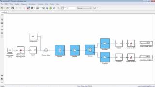
- Analyze Output Spectrum: By simulating the output, they will examine the resulting frequency components, specifically the sum and difference frequencies produced by the mixing process.
- Evaluate Performance: The simulation includes evaluating conversion loss, ensuring the output frequencies correspond with the expected sum and difference frequencies. This is important for assessing the efficiency and effectiveness of the mixer in practical applications.
Expected Results
Through this simulation, students should acquire an output spectrum that clearly marks the sum and difference frequencies along with insights into the conversion loss and overall linearity of the mixer design. Thorough understanding of these aspects ensures reliable and efficient circuitry in RF design.
Youtube Videos
Audio Book
Dive deep into the subject with an immersive audiobook experience.
Objective of the Simulation
Chapter 1 of 6
🔒 Unlock Audio Chapter
Sign up and enroll to access the full audio experience
Chapter Content
Objective: Design and simulate a basic diode mixer or double-balanced mixer for frequency conversion.
Detailed Explanation
The main aim of this simulation is to create and analyze a mixer circuit, specifically a basic diode mixer or a double-balanced mixer. These types of mixers are essential in RF systems for converting the frequency of signals. In simpler terms, a mixer takes two input signals (an RF signal and a local oscillator signal) and produces an output that contains frequencies that are the sum and difference of the input frequencies.
Examples & Analogies
Think of a mixer like a chef combining two ingredients to create a new dish. For instance, mixing sugar and water to create a syrup. Similarly, in electronics, the RF signal and the local oscillator signal are combined to create new signals at different frequencies.
Selecting the Mixer Type
Chapter 2 of 6
🔒 Unlock Audio Chapter
Sign up and enroll to access the full audio experience
Chapter Content
Simulation Steps:
1. Select Mixer Type: Choose between a passive diode mixer or an active mixer based on the requirements.
Detailed Explanation
In this step, you need to select the type of mixer that fits your design needs. There are two main categories: passive diode mixers, which use diodes to mix signals without requiring additional power supply, and active mixers, which use amplifying elements to improve performance but need power. The choice depends on several factors, including required performance, available power supply, and application.
Examples & Analogies
Imagine you are choosing a light bulb for your home. A standard bulb (passive) works well in most situations without needing extra power, while an LED bulb (active) might be brighter but requires electricity to work. Similarly, you'll choose the mixer based on performance needs and power availability.
Applying Input Signals
Chapter 3 of 6
🔒 Unlock Audio Chapter
Sign up and enroll to access the full audio experience
Chapter Content
- Input Signals: Apply an RF signal and a local oscillator (LO) signal to the mixer.
Detailed Explanation
This step involves setting up the signals that will enter the mixer. The RF signal is the original signal you want to process, while the local oscillator (LO) signal is another frequency that will help the mixer convert the RF signal to different frequencies. Once both signals are applied to the mixer, it prepares to produce the output frequencies.
Examples & Analogies
Think of this step as tuning a radio. The RF signal is like the radio station you want to listen to, and the LO signal is akin to your tune knob that helps you select the station. When properly mixed, you'll hear the music and talk shows (the output frequencies) just like the radio plays the chosen station.
Analyzing Output Spectrum
Chapter 4 of 6
🔒 Unlock Audio Chapter
Sign up and enroll to access the full audio experience
Chapter Content
- Analyze Output Spectrum: Simulate the output signal and examine the sum and difference frequencies (intermediate frequencies).
Detailed Explanation
In this step, after applying the input signals, you observe the output spectrum, which represents the frequencies generated by the mixer. You will specifically look for two new frequencies: one is the sum of the RF and LO signals, and the other is their difference. This analysis is crucial because it tells you how well the mixer is performing and whether it meets design specifications.
Examples & Analogies
This process is like listening for specific notes in a song to understand its melody. When musicians play together, they create a harmony (the new mixed frequencies), which you listen for to ensure they sound good together. Analyzing the output spectrum helps ensure your design achieves the desired outcome.
Evaluating Mixer Performance
Chapter 5 of 6
🔒 Unlock Audio Chapter
Sign up and enroll to access the full audio experience
Chapter Content
- Evaluate Performance: Analyze the conversion loss and ensure that the output frequencies match the expected sum and difference frequencies.
Detailed Explanation
Finally, you evaluate the overall performance of the mixer. This involves checking for conversion loss, which indicates how much signal strength is lost during the mixing process. You also need to ensure the output frequencies match your expectations. If they do not match, it could indicate an issue with the design or simulation setup.
Examples & Analogies
Imagine you are baking cookies. If you follow the recipe perfectly, you will produce delicious cookies (the expected output). But if you forget an ingredient or mix the wrong amounts, the cookies will turn out differently (unexpected output). Evaluating the mixer's performance is like tasting your cookies to ensure they are just right.
Expected Results
Chapter 6 of 6
🔒 Unlock Audio Chapter
Sign up and enroll to access the full audio experience
Chapter Content
Expected Results: The simulation should show the output spectrum with the expected sum and difference frequencies and provide information on conversion loss and linearity.
Detailed Explanation
After running the simulation, you should see a clear output spectrum that displays the expected sum and difference frequencies derived from the inputs. Additionally, you will obtain data regarding conversion loss and linearity, which inform you how efficient and accurate your mixer design is. These results help in verifying whether the mixer meets the specifications required for practical applications.
Examples & Analogies
It's like getting feedback after a presentation. If your audience gives you thumbs up and tells you that your points were clear and engaging (the output spectrum), you know you did a good job. Similarly, seeing the expected results from the simulation confirms that your design works as intended.
Key Concepts
-
RF Mixer: A fundamental component that combines RF signals for frequency conversion.
-
Conversion Loss: Indicates the efficiency of mixers by quantifying signal loss during frequency conversion.
-
Output Spectrum: The distribution of frequencies produced by the mixing process, showing sum and difference frequencies.
Examples & Applications
An RF mixer can allow a signal of 900 MHz (RF) mixed with a 100 MHz (LO) signal to produce output signals at 800 MHz (900-100) and 1000 MHz (900+100).
In radio receivers, mixers convert the desired RF signal to an intermediate frequency, making further processing easier.
Memory Aids
Interactive tools to help you remember key concepts
Rhymes
Mixers combine signals with ease, / Sum and difference, they aim to please!
Stories
Imagine a chef mixing fruit juices (RF signals) with a splash of soda (LO), creating a refreshing new drink (output frequencies), transforming flavors just like a mixer transforms signals.
Memory Tools
Remember the acronym 'MIX' - 'M': Mix two signals, 'I': Identify output, 'X': Evaluate performance.
Acronyms
MIX
for Mixer types
for Input signals
for eXpected results.
Flash Cards
Glossary
- RF Mixer
A device that combines two different frequency signals to produce new frequency components, specifically the sum and difference frequencies.
- Conversion Loss
The measure of loss of signal power resulting from the mixing process of an RF mixer.
- Local Oscillator (LO)
A signal that mixes with the RF input to produce new frequencies in RF circuitry.
- Intermediate Frequency (IF)
The frequency obtained after mixing, often used for further processing in receivers.
- Passive Diode Mixer
A simple type of mixer that utilizes diodes to achieve frequency mixing without amplification.
- Active Mixer
A mixer that incorporates amplifying devices to enhance performance compared to passive mixers.
Reference links
Supplementary resources to enhance your learning experience.