
Simulating an RF Amplifier
Interactive Audio Lesson
Listen to a student-teacher conversation explaining the topic in a relatable way.
Choosing an Active Device
🔒 Unlock Audio Lesson
Sign up and enroll to listen to this audio lesson

To start off, can anyone tell me why the choice of an active device is crucial in designing an RF amplifier?

I think it influences the amplifier's characteristics like gain and bandwidth.
Exactly! The choice affects gain, noise figure, and even distortion. What types of devices are we typically looking at?

We usually consider BJTs or FETs!
Right! BJTs and FETs have different characteristics, especially at high frequencies. For example, FETs are often preferable in RF applications for their higher input impedance. Remember the acronym FET for Frequency Efficient Transistor.

So, what should we look for in the specifications?
You’ll want to check parameters like gain bandwidth product and maximum frequency. Let's summarize: Choose a device based on application requirements, considering gain, bandwidth, and impedance.
Setting the Biasing
🔒 Unlock Audio Lesson
Sign up and enroll to listen to this audio lesson

Now that we've chosen our active device, what’s the next step?

Setting the biasing, right?
Correct! Biasing ensures the amplifier operates in the active region. Why is that significant?
It determines how well the amplifier can respond to varying input signals!
Exactly! Proper biasing is critical for avoiding distortion. Remember, we want our amplifier to amplify signals linearly. If we bias incorrectly, what might happen?
It could cut off the signal peaks or cause distortion?
Exactly! To ensure proper biasing, we usually use a biasing network. Let's summarize: Set up the biasing correctly to ensure reliable and linear operation.
Frequency Sweep and Analysis
🔒 Unlock Audio Lesson
Sign up and enroll to listen to this audio lesson
Next up, let's discuss how to perform a frequency sweep. Why do we need to do this in our simulations?
To see how gain varies with frequency!
Exactly! A frequency sweep helps us analyze the gain and the bandwidth of the amplifier. Can anyone tell me what bandwidth means?
It refers to the range of frequencies over which the amplifier operates effectively?
Exactly! During a frequency sweep, we can gather data on how our amplifier's gain changes across frequencies. Remember, bandwidth is typically defined by the 3dB points on our gain curve.
What should we focus on when analyzing the plot?
Focus on identifying the peak gain and the bandwidth range. Let's summarize: Conduct a frequency sweep to understand the amplifier's performance across frequency ranges.
Harmonics and Distortion Analysis
🔒 Unlock Audio Lesson
Sign up and enroll to listen to this audio lesson
Lastly, we must analyze the output for harmonics and distortion. Why do we do this?
To ensure the amplifier maintains linearity and does not distort the signal?
That's right! Distortion can severely impact signal integrity. What are some ways we could observe this?
We could look at the output waveform and check for clipping?
Exactly! Also, we can analyze the frequency spectrum to identify unwanted harmonics. Let's summarize: Check for distortion to ensure your amplifier operates as intended.
Conclusion and Key Takeaways
🔒 Unlock Audio Lesson
Sign up and enroll to listen to this audio lesson
To conclude our session on simulating an RF amplifier, who can recap the steps we've learned?
First, we choose an active device, then set the biasing to ensure proper operation.
Next, we conduct a frequency sweep to analyze gain and bandwidth.
Finally, we check for any harmonics or distortion in the output.
Excellent recap! Remember, simulating an RF amplifier is a crucial step in ensuring good design practice. Apply these insights in your future projects!
Introduction & Overview
Read summaries of the section's main ideas at different levels of detail.
Quick Overview
Standard
The section provides a detailed overview of the process of simulating an RF amplifier, including selecting an active device, setting biasing networks, conducting frequency sweeps, and analyzing distortion. By following these steps, learners can gain insights into the amplifier's gain, bandwidth, and overall performance, essential for optimizing RF designs.
Detailed
Simulating an RF Amplifier
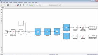
In this section, we focus on the practical steps involved in simulating an RF amplifier, which is crucial for understanding its performance at high frequencies. The objective is to design a basic amplifier, such as a common-emitter or common-source amplifier, by following a structured approach:
- Choose an Active Device: Start by selecting a suitable transistor or Field Effect Transistor (FET) that meets the design requirements.
- Set the Biasing: Proper biasing is essential for the transistor to function in the correct region — typically the active region for BJTs and the saturation region for FETs.
- Frequency Sweep: The next step involves simulating the amplifier's frequency response by sweeping the input frequencies. This allows the designer to analyze the gain and bandwidth, which are critical performance metrics.
- Analyze Harmonics and Distortion: Finally, a critical analysis of the output for any distortion or non-linearity at various signal levels is essential to verify that the amplifier operates as expected.
By completing these simulation steps, engineers can visualize the gain vs. frequency response, identify the 3dB bandwidth, and assess any distortion present at higher input signal levels. This practical exercise is fundamental for RF amplifier design, as it helps ensure optimal performance in real-world applications.
Youtube Videos
Audio Book
Dive deep into the subject with an immersive audiobook experience.
Objective of the Simulation
Chapter 1 of 6
🔒 Unlock Audio Chapter
Sign up and enroll to access the full audio experience
Chapter Content
Objective: Design and simulate a basic RF amplifier, such as a common-emitter amplifier or common-source amplifier, to understand its performance at high frequencies.
Detailed Explanation
The main goal of this simulation is to create an RF amplifier—specifically a common-emitter amplifier or a common-source amplifier. These types of amplifiers are widely used in RF applications because they can effectively amplify weak signals while maintaining good performance at high frequencies. Understanding how these amplifiers function will help us predict how they will behave in actual circuits.
Examples & Analogies
Think of the amplifier like a megaphone. Just as a megaphone takes a soft voice and makes it louder for a larger audience, an RF amplifier takes a weak radio signal and boosts it so it can be transmitted over long distances. Understanding how to design and simulate these amplifiers ensures that the signal is strong enough without becoming distorted.
Simulation Step 1: Choose an Active Device
Chapter 2 of 6
🔒 Unlock Audio Chapter
Sign up and enroll to access the full audio experience
Chapter Content
- Choose an Active Device: Select a transistor or FET for the amplifier.
Detailed Explanation
The first step in simulating an RF amplifier is to select an appropriate active device, which can be a bipolar junction transistor (BJT) or a field-effect transistor (FET). The choice of device is crucial because it affects the amplifier's performance characteristics such as gain, bandwidth, and linearity. Each type of transistor has different properties that can suit specific applications.
Examples & Analogies
Choosing an active device is like selecting the right tool for a job. If you're building a wooden chair, you wouldn't use a hammer to screw in bolts; instead, you would choose a screwdriver. Similarly, selecting the right type of transistor is essential for ensuring the amplifier performs as needed.
Simulation Step 2: Set the Biasing
Chapter 3 of 6
🔒 Unlock Audio Chapter
Sign up and enroll to access the full audio experience
Chapter Content
- Set the Biasing: Use biasing networks to ensure the transistor operates in the correct region (e.g., active region for a BJT or saturation region for a FET).
Detailed Explanation
The second step involves setting the correct biasing for the selected transistor or FET. Biasing ensures that the active device operates in the correct region of its characteristics—for instance, in the active region for BJTs or the saturation region for FETs. Proper biasing is critical because it influences the amplifier's stability and performance, particularly in high-frequency applications.
Examples & Analogies
Think of biasing like tuning a musical instrument. If a guitar string is too loose or too tight, it won't produce the right sound. Similarly, if a transistor isn't properly biased, it won't amplify signals correctly, leading to poor performance.
Simulation Step 3: Frequency Sweep
Chapter 4 of 6
🔒 Unlock Audio Chapter
Sign up and enroll to access the full audio experience
Chapter Content
- Frequency Sweep: Simulate the frequency response of the amplifier by sweeping the input frequency and analyzing the gain and bandwidth.
Detailed Explanation
The third step is to conduct a frequency sweep, which involves testing how the amplifier responds to different input frequencies. This helps in analyzing the amplifier's gain (how much it boosts the signal) and bandwidth (range of frequencies over which it operates effectively). Understanding the frequency response is vital for determining the amplifier's effectiveness in real-world applications.
Examples & Analogies
Imagine you’re testing a speaker's performance by playing various music genres. Some songs might sound clearer than others depending on the speaker's range. Similarly, a frequency sweep for an amplifier is like testing how well it 'plays' different signals across a spectrum of frequencies.
Simulation Step 4: Analyze Harmonics and Distortion
Chapter 5 of 6
🔒 Unlock Audio Chapter
Sign up and enroll to access the full audio experience
Chapter Content
- Analyze Harmonics and Distortion: Check for any distortion in the output and ensure the amplifier remains linear.
Detailed Explanation
Finally, analyzing harmonics and distortion involves checking whether the output signal is clean and undistorted when compared to the input. An ideal amplifier operates linearly, meaning that the output is a direct amplification of the input without unexpected alterations. Distortion can lead to signal degradation, compromising the quality of the output.
Examples & Analogies
Consider a professional singer. If they sing out of tune or off-key, it distorts the original melody. Similarly, if an RF amplifier introduces distortion, it alters the original signal being amplified, which can cause problems in communication systems.
Expected Results
Chapter 6 of 6
🔒 Unlock Audio Chapter
Sign up and enroll to access the full audio experience
Chapter Content
Expected Results: The simulation should show the gain vs. frequency response, the 3dB bandwidth, and any distortion at higher input signal levels.
Detailed Explanation
The expected results from the simulation are crucial for confirming that the design meets the required specifications. You should see a graph showing the relationship between gain and frequency, encompassing the 3dB bandwidth, which indicates where the amplifier starts to lose effectiveness. Checking for distortion at higher input levels ensures that the amplifier can handle stronger signals without compromising performance.
Examples & Analogies
Imagine baking a cake. If you follow the recipe perfectly, you expect a delicious cake to exit the oven. Similarly, after running the simulation, you expect to see clear results—a solid gain response, a designated bandwidth, and no distortion—indicating that the amplifier design was successful.
Key Concepts
-
Active Device: A component requiring external power to operate.
-
Biasing: The adjustment of operating conditions for a device to function correctly.
-
Frequency Sweep: A method to analyze performance across varying frequencies.
-
Distortion: Alteration of signal quality affecting integrity.
-
Gain: The ratio of output power to input power in amplification.
-
Bandwidth: Effective frequency range of an amplifier.
Examples & Applications
An RF amplifier circuit design involving a BJT configured as a common-emitter amplifier.
Simulating the frequency response of an RF amplifier to determine its gain at various frequencies.
Memory Aids
Interactive tools to help you remember key concepts
Rhymes
Active devices and biasing set the stage, / For amplifiers to engage and perform at every age.
Stories
Imagine setting up a concert: the active device is the singer, biasing is the microphone setup to ensure the singer's best voice is heard, while the frequency sweep is like adjusting the sound levels to ensure the music flows smoothly across all notes.
Memory Tools
Remember A-B-F-D for our amplifier simulation steps: Active device, Biasing, Frequency sweep, and Distortion analysis.
Acronyms
Use G-BAD to remember
Gain
Bandwidth
Active device
and Distortion as parameters to analyze in RF amplifiers.
Flash Cards
Glossary
- Active Device
An electronic component that requires an external power source to operate and can control the flow of current, such as transistors.
- Biasing
The process of setting a transistor's or FET's operating voltage and current levels to ensure it functions in the active region.
- Frequency Sweep
A technique involving the gradual variation of input signal frequency to analyze the frequency response and performance of a circuit.
- Distortion
Any alteration in the original waveform of the signal due to non-linear amplification, which can lead to signal integrity problems.
- Gain
The ratio of the output signal power to the input signal power, expressed in decibels, representing the amplification capability of an amplifier.
- Bandwidth
The range of frequencies over which the amplifier can operate effectively, commonly defined by the 3dB points on the gain curve.
Reference links
Supplementary resources to enhance your learning experience.