
Hands-on Simulations of RF and HF Circuits
Interactive Audio Lesson
Listen to a student-teacher conversation explaining the topic in a relatable way.
Introduction to Circuit Simulation in RF and HF Design
🔒 Unlock Audio Lesson
Sign up and enroll to listen to this audio lesson

Let’s start our discussion on RF and HF circuit design. Why do you think simulation is crucial in this field?

So we can predict how the circuit will perform without building it?
Exactly! Simulation helps in anticipating performance and troubleshooting issues. It not only saves time and resources but allows for component optimization. Can anyone list out some factors that are taken into account during simulation?

Frequency response and gain seem really important!

What about impedance matching?
Great points! Impedance matching is critical for maximum power transfer. Remember the acronym 'FAG' — Frequency response, Amplifier gain, and impedance Matching — to recall these key concepts. Let’s summarize: simulations save time and resources, optimize designs, and help identify flaws early.
Overview of RF and HF Simulation Tools
🔒 Unlock Audio Lesson
Sign up and enroll to listen to this audio lesson

Now, let’s move on to the simulation tools. Can anyone name some popular tools used for RF and HF design?
I’ve heard of SPICE and ADS.

What about Microwave Office?
All correct! SPICE is great for both analog and RF circuits, while ADS is powerful for high-frequency designs. Remember that each tool serves specific purposes. What do you think the advantages of using these simulations are?
They help reduce costs and time, right?
Exactly! Simulations are time and cost-efficient and allow testing under various conditions. To remember, use the acronym 'COST' — Cost savings, Optimization, Simulating tasks, and Troubleshooting.
Key Concepts in RF and HF Circuit Simulation
🔒 Unlock Audio Lesson
Sign up and enroll to listen to this audio lesson
Let’s delve into some key concepts essential for effective RF and HF circuit simulation. What is impedance matching?
It’s about matching the impedance of components to ensure maximum power transfer.
Correct! Now why is gain important in amplifiers?
Because we need them to amplify signals without distortion!
Precisely! Maintaining gain and avoiding distortion is crucial for linearity. What kind of simulations would you run to check for gain and distortion?
We can simulate amplifiers to see their gain and analyze for distortion at high signal levels.
Great insight! Remember the mnemonic 'GAM' for Gain, Amplifiers, and Matching to help you recall these key points. Let’s summarize our session: impedance matching, gain importance, and ensuring amplifiers maintain linearity are crucial in simulations.
Practical Simulations of RF and HF Circuits
🔒 Unlock Audio Lesson
Sign up and enroll to listen to this audio lesson
Now, let’s look into practical applications. What’s the first step in simulating an RF amplifier?
We need to choose the active device!
Correct! After choosing, what’s next?
Setting up the biasing networks?
Yes! Proper biasing ensures that the amplifier works in the correct region. And then?
Performing a frequency sweep to analyze response.
Exactly! Remember the acronym 'BAS' — Biasing, Active device selection, and Sweep for analyzing frequency response. Let’s summarize: the process starts with choosing components, setting up networks, and then analyzing the frequency response.
Introduction & Overview
Read summaries of the section's main ideas at different levels of detail.
Quick Overview
Standard
Hands-on simulations are crucial in RF and HF circuit design for verifying designs, predicting performance, and troubleshooting issues before physical implementation. This section discusses various simulation tools available, their benefits, and key concepts such as impedance matching, gain, frequency response, and more.
Detailed
Hands-on Simulations of RF and HF Circuits
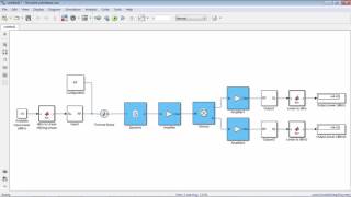
In RF and HF circuit design, simulation serves as a vital step in verifying designs and troubleshooting potential issues before implementing physical prototypes. Simulation tools—such as SPICE, ADS, and Microwave Office—encompass a virtual environment where designers can test and analyze the characteristics of components and circuits under various conditions.
Simulation techniques enable practitioners to optimize circuit parameters, such as frequency response and gain, while also addressing important factors, including impedance matching and linearity in amplifiers. This section outlines the various simulation tools, their benefits, and practical simulations of key RF components (amplifiers, mixers, filters), serving as a foundation for in-depth understanding and application in real-world designs.
Youtube Videos
Audio Book
Dive deep into the subject with an immersive audiobook experience.
Introduction to Circuit Simulation
Chapter 1 of 4
🔒 Unlock Audio Chapter
Sign up and enroll to access the full audio experience
Chapter Content
In RF and HF circuit design, simulation plays a crucial role in verifying designs, predicting performance, and troubleshooting issues before physical implementation. Simulation tools help engineers model and analyze complex circuits by taking into account factors such as frequency response, impedance matching, gain, and stability.
Hands-on simulations allow students and professionals to test different circuit configurations, optimize components, and understand the behavior of circuits under various conditions. This chapter focuses on the simulation techniques and tools used for RF and HF circuits, as well as practical simulations of common RF components like amplifiers, mixers, and filters.
Detailed Explanation
Circuit simulation is an essential part of designing RF (radio frequency) and HF (high frequency) circuits. It helps engineers check their circuit designs to ensure that they will work as intended before they physically build them. By using simulation tools, engineers can account for the intricate behavior of active components like transistors and passive elements like capacitors under varying conditions. Hands-on simulations enable students and professionals to experiment with different circuit setups, fine-tune components, and analyze how circuits respond to changes in the environment.
Examples & Analogies
Think of circuit simulation like using a flight simulator before piloting a real aircraft. Just as pilots practice on simulators to understand flight dynamics, engineers use circuit simulations to foresee how their designs might perform in practice. This approach saves time and resources by identifying potential issues early.
Overview of RF and HF Simulation Tools
Chapter 2 of 4
🔒 Unlock Audio Chapter
Sign up and enroll to access the full audio experience
Chapter Content
Several simulation tools are available to help in designing and testing RF and HF circuits. These tools provide a virtual environment where components can be selected, and circuit behavior can be analyzed under different conditions.
Detailed Explanation
There are various software tools designed specifically for simulating RF and HF circuits. These tools allow engineers to create virtual models of their circuits. By selecting different components and changing circuit conditions within the software, users can observe how the circuit would perform in real life without the need to physically build anything. This capability is particularly useful for complex designs and high-frequency applications.
Examples & Analogies
Imagine these simulation tools as a digital workshop where you can tweak and turn every part of a machine without risking damage to any actual equipment. Just like a mechanic can visualize the assembly of a car engine on a computer before bringing the parts together, engineers can visualize and test their circuit designs before proceeding to actual construction.
Common Simulation Tools for RF and HF Circuits
Chapter 3 of 4
🔒 Unlock Audio Chapter
Sign up and enroll to access the full audio experience
Chapter Content
● SPICE (Simulation Program with Integrated Circuit Emphasis): SPICE is a widely used simulation tool for analog and RF circuits...
● Advanced Design System (ADS)...
● Microwave Office (MWO)...
● LTspice...
● Ansys HFSS...
Detailed Explanation
There are several key tools that engineers use for RF and HF circuit simulations, each serving different purposes. SPICE is a basic but powerful tool that allows the simulation of both analog and RF circuits. ADS and MWO provide focused solutions for high-frequency and microwave circuit designs, allowing engineers to perform detailed analyses and optimizations. LTspice is a free tool that simplifies the simulation of smaller scale circuits, making it more accessible for learners and hobbyists. Lastly, Ansys HFSS specializes in simulating 3D structures useful for antenna design and high-frequency applications.
Examples & Analogies
Consider these tools as different specialists in a clinic: just like each doctor focuses on a specific area of health, each simulation tool is tailored for particular types of circuit analysis. SPICE is like a general practitioner, addressing basic needs, while ADS and MWO are akin to specialists focusing on advanced conditions like high-frequency operations.
Benefits of Simulation
Chapter 4 of 4
🔒 Unlock Audio Chapter
Sign up and enroll to access the full audio experience
Chapter Content
● Time and Cost Efficiency: Simulation allows engineers to evaluate the performance of their designs before committing to physical prototypes, saving both time and money.
● Optimization: Simulations help in optimizing components and design parameters to achieve the best performance.
● Troubleshooting: Simulation tools enable the identification of design flaws and performance issues early in the design process.
Detailed Explanation
Simulating circuits brings numerous benefits. First, it saves both time and money by allowing engineers to refine their designs without the need to build tangible prototypes. Second, simulations enable optimization of the individual components, ensuring that every part works well together, enhancing overall circuit performance. Lastly, simulation tools can quickly reveal design flaws and issues, allowing engineers to make necessary adjustments before physical implementation.
Examples & Analogies
Think of it like baking a cake: you might want to sample the batter before it goes in the oven. Simulation lets engineers sample their designs in a virtual 'kitchen,' adjusting ingredients (or components) as needed before the cake (circuit) is finalized and baked (constructed). This way, they can ensure they achieve the perfect flavor (performance) without wasting time or ingredients (materials).
Key Concepts
-
Circuit Simulation: A method used to model and analyze behavior.
-
Impedance Matching: Ensures maximum power transfer.
-
Gain: Fundamental in amplifiers for signal amplification.
-
Frequency Response: Shows how systems react to different frequencies.
-
Linear Amplifiers: Maintain constant gain and avoid distortion.
Examples & Applications
Simulation of an RF amplifier to analyze its gain at different frequencies.
Design of a band-pass filter to evaluate its frequency response.
Memory Aids
Interactive tools to help you remember key concepts
Rhymes
To match impedance and gain, signals won't go down the drain.
Stories
Imagine a team of engineers gathering around their simulation tools, deciding to test various configurations in a virtual lab. They optimize, correct, and innovate before ever touching a physical piece of hardware, ensuring that when they do, their designs are sound.
Memory Tools
Remember 'FAG': Frequency response, Amplifier gain, and impedance Matching for crucial RF design principles.
Acronyms
COST
Cost savings
Optimization
Simulating tasks
Troubleshooting.
Flash Cards
Glossary
- Circuit Simulation
A method of using software to model the behavior of circuits.
- Impedance Matching
The process of matching circuit impedances to maximize power transfer.
- Gain
The ratio of output power to input power in an amplifier.
- Frequency Response
The output spectrum of a system as a function of frequency.
- Linear Amplifier
An amplifier that maintains a constant gain over a specific input range.
- Simulation Tools
Software programs used to model and analyze circuit designs.
Reference links
Supplementary resources to enhance your learning experience.