
Simulating an RF Filter
Interactive Audio Lesson
Listen to a student-teacher conversation explaining the topic in a relatable way.
Introduction to RF Filters
🔒 Unlock Audio Lesson
Sign up and enroll to listen to this audio lesson

Today, we will explore RF filters and their role in frequency selection. Can anyone share what they know about these filters?

I think RF filters help to allow certain frequencies to pass while blocking others.
Exactly! We typically focus on low-pass, high-pass, and band-pass filters. Lets remember their functions with the acronym 'LHP'—Low, High, Pass.

So, what does each type do specifically?
'Low-pass filters allow frequencies below a certain cutoff to pass, high-pass filters do the opposite, and band-pass filters allow a specific range of frequencies to pass. Can someone tell me why this is important in RF design?'

It helps in minimizing interference and optimizing signal clarity!
That's right! Let's transition to how we can simulate these filters effectively.
Simulation Steps for RF Filters
🔒 Unlock Audio Lesson
Sign up and enroll to listen to this audio lesson

We will discuss the steps to simulate RF filters. First, we need to choose our filter type and define the cutoff frequencies. Why do you think cutoff frequencies are crucial?

They dictate which signals get through and which are blocked.
Right! Next is component selection—how do we decide what components to use?
Based on the frequencies we wish to target, like choosing inductors and capacitors?
Exactly! After that, we simulate the frequency response. Why do we perform frequency sweeps?
To analyze how the filter performs across a range of frequencies.
Correct! Finally, we evaluate the filter's characteristics—who can summarize what we should look for?
We need to check the passband, stopband, and transition band!
Excellent recap! Understanding these steps helps you design effective filters.
Evaluating Simulation Results
🔒 Unlock Audio Lesson
Sign up and enroll to listen to this audio lesson
Let's now talk about the expected results of our simulations. What do we anticipate observing in the frequency response graph of a filter?
We should see clear indicators of cutoff frequencies.
Correct! We also want to note the quality factor, or Q. Can anyone explain what Q indicates?
It measures how well a filter can select a narrow range of frequencies!
Exactly! Complex filters might display different shapes in the passband and stopband. Who can tell me why this is significant?
It reflects the filter's effectiveness in real applications, especially in communication systems.
Spot on! The more accurately we can simulate and understand these characteristics, the better our designs will perform in practice.
Introduction & Overview
Read summaries of the section's main ideas at different levels of detail.
Quick Overview
Standard
The section provides a comprehensive guide on simulating RF filters including design considerations, the selection of components, and an analysis of the filter's frequency response. Key elements such as cutoff frequencies and filter characteristics are emphasized as vital components in RF design.
Detailed
Detailed Summary
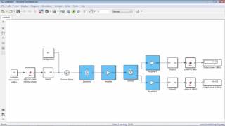
In this section, we delve into the practical aspects of simulating RF filters—essential components in RF and HF circuit design that determine how signals are processed within communication systems. The objective is to design and simulate different RF filters (low-pass, high-pass, and band-pass) to comprehend their performance metrics, specifically focusing on the frequency response. The simulation involves four fundamental steps: first, selecting the appropriate filter type and defining its cutoff frequencies; second, carefully choosing the components (including inductors and capacitors) based on those frequencies; third, executing a frequency sweep in the simulation environment to analyze performance; and finally evaluating critical characteristics such as the passband, stopband, and transition band. The section highlights the expected outcomes from these simulations, which include curve representations of frequency response showcasing cutoff frequency, quality factor (Q), and the distinct shapes of the filter's passband and stopband. This simulation practice is crucial for understanding how filters behave in real-world applications and ensures that the designs meet the necessary specifications for effective signal processing.
Youtube Videos
Audio Book
Dive deep into the subject with an immersive audiobook experience.
Objective of RF Filter Simulation
Chapter 1 of 6
🔒 Unlock Audio Chapter
Sign up and enroll to access the full audio experience
Chapter Content
Objective: Design and simulate an RF filter, such as a low-pass, high-pass, or band-pass filter.
Detailed Explanation
The objective of simulating an RF filter is to understand how it functions in allowing or blocking specific frequency ranges of signals. RF filters are crucial for managing signal integrity in various applications, such as radios and communication devices. By designing and simulating the filter, students can explore how different filter types affect frequency signals.
Examples & Analogies
Think of an RF filter like a bouncer at a club. Just as the bouncer decides who gets in based on certain criteria, the RF filter manages which signals are allowed to pass through based on their frequency, ensuring only the desired signals reach the output.
Filter Design Process
Chapter 2 of 6
🔒 Unlock Audio Chapter
Sign up and enroll to access the full audio experience
Chapter Content
Simulation Steps:
1. Filter Design: Choose the appropriate filter type and define the cutoff frequencies.
Detailed Explanation
The first step in simulating an RF filter is to decide what type of filter to create – low-pass, high-pass, or band-pass. Each filter type serves a unique purpose in signal processing. Next, the cutoff frequencies need to be defined, as they determine the frequency range that the filter will either allow or block. This step is critical because the performance of the filter greatly depends on these specifications.
Examples & Analogies
Imagine you’re setting up a movie night with friends. You could choose a specific genre, like action or comedy, determining which films are 'in' and which ones are 'out.' Similarly, selecting a filter type and cutoff frequency defines which signal frequencies will pass through the filter.
Component Selection for the Filter
Chapter 3 of 6
🔒 Unlock Audio Chapter
Sign up and enroll to access the full audio experience
Chapter Content
- Component Selection: Select components (e.g., inductors, capacitors) for the filter based on the desired cutoff frequency.
Detailed Explanation
After determining the filter type and cutoff frequencies, the next step involves selecting the right components to build the filter. Components like inductors and capacitors play vital roles in defining the filter's characteristics. The choice of these components directly impacts how well the filter performs at the designated frequencies.
Examples & Analogies
Constructing an RF filter is like building a sandwich. You need the right ingredients (components) to make a delicious sandwich (filter). Depending on your taste (frequency requirements), you may choose lettuce (capacitor) for crispness or turkey (inductor) for a hearty flavor!
Simulating Frequency Response
Chapter 4 of 6
🔒 Unlock Audio Chapter
Sign up and enroll to access the full audio experience
Chapter Content
- Simulate Frequency Response: Perform a frequency sweep to analyze the filter’s performance.
Detailed Explanation
Performing a frequency sweep involves testing how the filter responds to a range of frequencies. During this simulation step, the performance of the filter can be identified by observing how effectively it allows certain frequencies to pass while rejecting others. This step is key to understanding the filter's behavior in real scenarios.
Examples & Analogies
Think of the frequency sweep as testing out a new phone's sound system with different music genres. You play various songs to see how well the speakers handle each type of music and adjust the settings accordingly, just as you assess how well a filter manages different signal frequencies.
Analyzing Filter Characteristics
Chapter 5 of 6
🔒 Unlock Audio Chapter
Sign up and enroll to access the full audio experience
Chapter Content
- Analyze Filter Characteristics: Evaluate the filter’s passband, stopband, and transition band.
Detailed Explanation
In the final step, it's important to analyze the key characteristics of the filter, such as the passband (the frequencies it allows), stopband (the frequencies it blocks), and the transition band (the frequencies it starts to reject or allow). Analyzing these characteristics provides insight into the filter's performance and effectiveness in practical applications.
Examples & Analogies
Analyzing filter characteristics is similar to checking out the reviews for a new restaurant. You want to know not only what dishes they serve (passband) but also what they don’t serve (stopband) and how well the menu changes (transition band) to meet customer preferences.
Expected Results of the Simulation
Chapter 6 of 6
🔒 Unlock Audio Chapter
Sign up and enroll to access the full audio experience
Chapter Content
Expected Results: The simulation should show the frequency response, including the cutoff frequency, quality factor (Q), and the shape of the filter’s passband and stopband.
Detailed Explanation
Once the simulation is complete, you should be able to see the frequency response graphically represented, illustrating key metrics such as the cutoff frequency and quality factor (Q), which indicates how selective the filter is. The shape of both the passband and stopband will also be evident, showcasing how well the filter functions across the designated frequencies.
Examples & Analogies
Receiving the expected results from the simulation is like checking your exam results after intense studying. You see the grades that reflect your preparation (the filter's performance) and confirm whether you met your learning goals (the filter's specifications).
Key Concepts
-
Filter Design: The process of choosing the appropriate filter type and cutoff frequencies.
-
Component Selection: Choosing inductors and capacitors to meet frequency requirements.
-
Frequency Response: Analyzing how the filter performs over a range of different frequencies.
-
Filter Characteristics: Evaluating the passband, stopband, and transition band of the filter.
Examples & Applications
Designing a band-pass filter to allow signals between 100 MHz and 200 MHz while blocking frequencies outside this range.
Simulating a low-pass filter with a cutoff frequency of 500 kHz to observe how high frequencies are attenuated.
Memory Aids
Interactive tools to help you remember key concepts
Rhymes
Filters work to clear the sound, letting good frequencies get around.
Stories
Imagine you’re at a concert. The bass (low frequencies) plays softly, while high-frequency sounds (like a whistle) are turned down; that's a low-pass filter in action!
Memory Tools
LHP for Low, High, Pass—types of RF filters to learn fast!
Acronyms
PST for Passband, Stopband, Transition band characteristics.
Flash Cards
Glossary
- RF Filter
A circuit that allows certain frequency ranges to pass and blocks others.
- Cutoff Frequency
The frequency at which the output signal starts to decline in magnitude.
- Passband
The frequency range where the filter allows signals to pass.
- Stopband
The frequency range that the filter blocks.
- Transition Band
The range between the passband and stopband where the filter response transitions.
- Quality Factor (Q)
A measure of how selective a filter is; higher Q values indicate a narrower passband.
Reference links
Supplementary resources to enhance your learning experience.