
Practical Simulations of RF and HF Circuits
Interactive Audio Lesson
Listen to a student-teacher conversation explaining the topic in a relatable way.
Simulating an RF Amplifier
🔒 Unlock Audio Lesson
Sign up and enroll to listen to this audio lesson

Today, we'll look at simulating an RF amplifier. The first step is to choose an active device, like a transistor or FET. Do any of you know how these devices affect performance?

I think the type of device will change the gain, right?
Exactly! The gain is directly related to the characteristics of the active device. Once we select the device, we need to set the correct biasing. Can anyone explain why biasing is essential?

Biasing ensures that the transistor operates in the right region, like the active region for BJTs or saturation for FETs.
Well said! After biasing, we perform a frequency sweep. Who can tell me what a frequency sweep does?

It helps analyze how gain changes with input frequency!
Right again! Finally, we analyze any harmonics and distortion. Let’s wrap this session by summarizing key steps: choosing the device, setting bias, sweeping frequency, and checking for distortion.
Simulating an RF Mixer
🔒 Unlock Audio Lesson
Sign up and enroll to listen to this audio lesson

Next, let's focus on RF mixers. The first step is to select the type of mixer. What do you think influences this choice?

It could depend on whether we need a passive or active mixer based on the application's requirements?
Correct! After selecting a mixer type, we apply input RF and LO signals. What do we analyze next?
The output spectrum, right? We need to verify the sum and difference frequencies.
Exactly! And we also evaluate conversion loss. Remember this: understanding each output frequency helps identify how our mixer is performing.
So, the mixer performance is vital for applications like receivers!
Yes! In summary, for RF mixers, we must choose type, apply signals, analyze output spectrum, and evaluate performance. Well done!
Simulating an RF Filter
🔒 Unlock Audio Lesson
Sign up and enroll to listen to this audio lesson
Now let's dive into simulating RF filters. What’s our first task?
Choosing the filter type, like low-pass or high-pass, based on what we need to filter!
Exactly! Next, we select components. How do component choices affect filter design?
They should match the desired cutoff frequencies!
Yes! After that, we perform a frequency sweep to analyze performance. Who can describe what we’re looking for?
We're checking the passband, stopband, and transition characteristics?
Exactly! To sum up: We select filter type, choose components that match cutoff frequencies, and perform frequency analyses.
Introduction & Overview
Read summaries of the section's main ideas at different levels of detail.
Quick Overview
Standard
The section outlines practical simulation techniques for RF and HF circuits. It details the simulations of RF amplifiers, mixers, and filters, outlining specific steps to achieve desired performance characteristics. Key results and expectations from each simulation task are also discussed.
Detailed
Practical Simulations of RF and HF Circuits
In RF and HF circuit design, practical simulations serve as a crucial tool for understanding and verifying the performance of various components like amplifiers, mixers, and filters. This section delineates the key objectives and procedures involved in simulating these circuits.
Key Components of Simulation
- Simulating an RF Amplifier
- Objective: To design and simulate a basic RF amplifier (like common-emitter or common-source) to assess its performance at high frequencies.
- Steps: Include selecting an active device, setting biasing, conducting a frequency sweep, and analyzing harmonics and distortion.
- Expected Results: The simulation should yield gain vs. frequency response, revealing 3dB bandwidth and distortion levels.
- Simulating an RF Mixer
- Objective: To design and simulate a mixer for frequency conversion.
- Steps: Choosing the mixer type, applying input signals, simulating the output spectrum, and evaluating performance characteristics like conversion loss.
- Expected Results: Insight into output spectrum along with sum and difference frequencies, alongside conversion loss metrics.
- Simulating an RF Filter
- Objective: To design and simulate an RF filter (low-pass, high-pass, or band-pass).
- Steps: Selecting the appropriate filter type, choosing components that align with defined cutoff frequencies, and simulating the frequency response.
- Expected Results: Understanding filter characteristics encompassing passband, stopband, and transition bandwidth.
Overall, this section emphasizes the importance of simulations in RF design, where analyzing various components helps in optimizing and verifying designs before implementation.
Youtube Videos
Audio Book
Dive deep into the subject with an immersive audiobook experience.
Simulating an RF Amplifier
Chapter 1 of 3
🔒 Unlock Audio Chapter
Sign up and enroll to access the full audio experience
Chapter Content
10.4.1 Simulating an RF Amplifier
Objective: Design and simulate a basic RF amplifier, such as a common-emitter amplifier or common-source amplifier, to understand its performance at high frequencies.
Simulation Steps:
1. Choose an Active Device: Select a transistor or FET for the amplifier.
2. Set the Biasing: Use biasing networks to ensure the transistor operates in the correct region (e.g., active region for a BJT or saturation region for a FET).
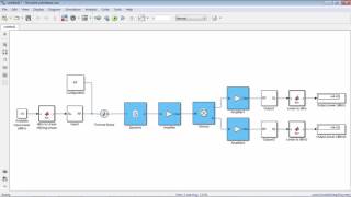
3. Frequency Sweep: Simulate the frequency response of the amplifier by sweeping the input frequency and analyzing the gain and bandwidth.
4. Analyze Harmonics and Distortion: Check for any distortion in the output and ensure the amplifier remains linear.
Expected Results: The simulation should show the gain vs. frequency response, the 3dB bandwidth, and any distortion at higher input signal levels.
Detailed Explanation
In this chunk, you learn how to simulate an RF amplifier step-by-step. First, you select the active device, such as a transistor. Next, you set up the biasing, which ensures that the transistor operates correctly for amplification. Then, you perform a frequency sweep to see how well the amplifier works across different frequencies, checking its gain and bandwidth. Finally, you analyze the output to spot any distortion, which can affect the quality of the signal. The expected outcome from this simulation includes a graph showing how gain varies with frequency and identifying any issues related to distortion.
Examples & Analogies
Think of this like tuning a musical instrument. Selecting the right instrument (choosing a transistor) is like choosing the type of guitar for a concert. Setting the biasing is like tuning the strings to ensure they produce the correct notes. Sweeping the frequency is akin to playing the instrument at various pitches to see how well it performs, and checking for distortion is like ensuring the sound isn't fuzzy or unclear when you play a loud chord.
Simulating an RF Mixer
Chapter 2 of 3
🔒 Unlock Audio Chapter
Sign up and enroll to access the full audio experience
Chapter Content
10.4.2 Simulating an RF Mixer
Objective: Design and simulate a basic diode mixer or double-balanced mixer for frequency conversion.
Simulation Steps:
1. Select Mixer Type: Choose between a passive diode mixer or an active mixer based on the requirements.
2. Input Signals: Apply an RF signal and a local oscillator (LO) signal to the mixer.
3. Analyze Output Spectrum: Simulate the output signal and examine the sum and difference frequencies (intermediate frequencies).
4. Evaluate Performance: Analyze the conversion loss and ensure that the output frequencies match the expected sum and difference frequencies.
Expected Results: The simulation should show the output spectrum with the expected sum and difference frequencies and provide information on conversion loss and linearity.
Detailed Explanation
In this chunk, you will simulate how an RF mixer functions. First, you will decide on a type of mixer to use, whether a passive diode mixer or an active one, based on the project needs. Next, you will feed the mixer an RF signal and a local oscillator signal, which act like musical notes that will be blended together. After inputting the signals, you analyze the resulting output spectrum to identify the sum (combined frequency) and difference (the frequency gap between the signals). Lastly, you check the performance by evaluating the conversion loss to see how much signal strength is lost during the mixing process. The expected results will display the output frequencies that confirm the mixing has occurred successfully.
Examples & Analogies
Imagine making a fruit smoothie. The RF signal is like a banana, and the local oscillator signal is like strawberries. When you blend them together, you're mixing the two flavors (frequencies) to create a new delicious smoothie (output signal). By tasting the smoothie, you can evaluate if the flavors (frequencies) are well balanced or if the banana overpowers the strawberries, just like checking for conversion loss in a mixer.
Simulating an RF Filter
Chapter 3 of 3
🔒 Unlock Audio Chapter
Sign up and enroll to access the full audio experience
Chapter Content
10.4.3 Simulating an RF Filter
Objective: Design and simulate an RF filter, such as a low-pass, high-pass, or band-pass filter.
Simulation Steps:
1. Filter Design: Choose the appropriate filter type and define the cutoff frequencies.
2. Component Selection: Select components (e.g., inductors, capacitors) for the filter based on the desired cutoff frequency.
3. Simulate Frequency Response: Perform a frequency sweep to analyze the filter’s performance.
4. Analyze Filter Characteristics: Evaluate the filter’s passband, stopband, and transition band.
Expected Results: The simulation should show the frequency response, including the cutoff frequency, quality factor (Q), and the shape of the filter’s passband and stopband.
Detailed Explanation
In this chunk, you will work on simulating an RF filter step-by-step. Start by designing the filter, which includes choosing the type of filter you need (low-pass, high-pass, etc.) and defining its cutoff frequencies. After that, select suitable components like inductors and capacitors that will help achieve the desired filter characteristics. Next, you will carry out a frequency sweep to see how the filter behaves under various frequencies, assessing its performance. Finally, evaluate characteristics like the passband (frequencies it allows) and stopband (frequencies it blocks) to ensure it meets design specifications.
Examples & Analogies
Think of an RF filter like a bouncer at a nightclub. The bouncer (the filter) decides who gets into the club (passband) and who doesn’t (stopband). By defining clear criteria for who is allowed in (cutoff frequencies), you ensure that the right crowd enjoys the show while unwanted guests are turned away. When you simulate the filter, it's like checking how well the bouncer does their job over different nights, ensuring they maintain good crowd control.
Key Concepts
-
Simulation of RF Amplifiers: Essential for analyzing gain and bandwidth performance.
-
RF Mixers: Crucial for frequency conversion processes in RF systems.
-
RF Filters: Key in selecting frequency characteristics to allow or block signals.
Examples & Applications
Simulating a common-emitter amplifier to determine its linearity and gain at various frequencies.
Analyzing a double-balanced mixer using provided RF and local oscillator signals to evaluate output frequencies.
Memory Aids
Interactive tools to help you remember key concepts
Rhymes
Amplify the signal high, with bias set to fly!
Stories
Imagine a radio station where amplifiers boost DJ's voice, while mixers blend different music tracks to create a melody. Filters then decide which tunes play on air!
Memory Tools
A-M-F: Amplifier, Mixer, Filter - components of RF simulations.
Acronyms
AMP
Active device
Matching bias
Performance check.
Flash Cards
Glossary
- RF Amplifier
A device used to increase the amplitude of radio frequency signals.
- Mixer
A circuit that combines two or more signals to generate new frequencies.
- Filter
An electronic component that allows certain frequencies to pass while blocking others.
- Biasing
The process of setting a transistor's operating point for optimal performance.
- Frequency Sweep
A process that involves changing the input frequency to analyze circuit behavior across a range of frequencies.
Reference links
Supplementary resources to enhance your learning experience.