
High Frequency Considerations
Enroll to start learning
You’ve not yet enrolled in this course. Please enroll for free to listen to audio lessons, classroom podcasts and take practice test.
Interactive Audio Lesson
Listen to a student-teacher conversation explaining the topic in a relatable way.
Parasitic Capacitances
🔒 Unlock Audio Lesson
Sign up and enroll to listen to this audio lesson

Today we're diving into parasitic capacitances, such as gate-to-source and gate-to-drain capacitances. Can anyone tell me why these might be important in a high-frequency amplifier?

I think it’s because they can alter how signals are processed?
Yes, exactly! These capacitances can affect the timing and response of signals. We call this the 'Miller effect'. Remember: **'Miller Magnifies'**. Great mnemonic! It helps us remember that these capacitances can amplify their influence within the amplifier circuit.

So, how do these capacitances change the overall gain?
Good question! As frequency increases, the impact of these capacitances becomes more pronounced, potentially reducing the voltage gain. Let's remember that: **'High Frequency, Low Gain'**. Can anyone recite that?
Output Conductance and Its Implications
🔒 Unlock Audio Lesson
Sign up and enroll to listen to this audio lesson

Next, let's discuss the output conductance, R_O, which represents the change in output current with respect to output voltage. Why do you think this parameter is essential?

I think it's related to how easily the amplifier can drive a load?
Exactly! A lower output conductance means the amplifier can drive loads more efficiently. To help remember, think: **'Low R_O, Strong Load'**. What can we say happens if R_O is higher?

It would be less efficient at driving loads?
Correct! The output conductance plays a crucial role in defining the amplifier's dynamic range at high frequencies.
Cutoff Frequencies
🔒 Unlock Audio Lesson
Sign up and enroll to listen to this audio lesson
Now, who can explain what we mean by low and upper cutoff frequencies?
Isn’t the lower cutoff the frequency below which the circuit doesn't respond well?
Correct! We define the lower cutoff frequency, f_cutoff(L), as defined by coupling capacitors and resistance. Remember: **'Low = Lack of Output'**. What about the upper cutoff?
That would be the frequency where gain starts dropping off due to capacitive effects?
Exactly! Upper cutoff, f_cutoff(U), considers both load resistance and parasitics. Think: **'High = Halt in Gain'**. So, knowing these points helps optimize amplifier design.
Frequency Response
🔒 Unlock Audio Lesson
Sign up and enroll to listen to this audio lesson
Finally, let's connect our discussion to frequency response. How does our understanding of cutoff frequencies affect performance?
Well, if we know the cutoff, we can adjust our design to maximize the usefulness of the amplifier!
Right! Adjusting capacitors and resistors can help us reach our desired frequency range. Let's remember: **'Tuning for the Tune'** means aligning frequency response to the needs of our application.
Can tuning also help with parasitics?
Absolutely, proper tuning can mitigate the effects of parasitics ensuring optimal performance across frequencies!
Application of Concepts
🔒 Unlock Audio Lesson
Sign up and enroll to listen to this audio lesson
Let’s contextualize everything we’ve discussed. Can anyone think of a scenario where high-frequency considerations matter?
In radio transmitters! High frequencies are crucial there, right?
Exactly! They need well-optimized amplifiers. Remember: **'Radio Ready, Frequency Steady'**. What else?
How about in smartphones? They deal with varying frequencies.
Spot on! Optimizing these parameters directly improves signal clarity. Understanding these concepts is paramount, especially in technology trends!
Introduction & Overview
Read summaries of the section's main ideas at different levels of detail.
Quick Overview
Standard
In this section, we explore the impact of high-frequency operation on common source amplifiers, particularly focusing on parasitic capacitances such as gate-to-source and gate-to-drain capacitances. We also consider the output conductance and its role in amplifier performance, wrapping up with insights on low and upper cutoff frequencies related to frequency response.
Detailed
High Frequency Considerations in Common Source Amplifiers
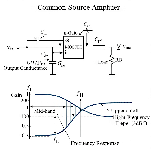
In high-frequency applications of common source amplifiers, parasitic capacitances—specifically gate-to-source and gate-to-drain capacitances—become significant. These capacitors influence the performance of the amplifier by coupling signal and introducing feedback effects, which manifest in the voltage gain and overall frequency response.
The output conductance, denoted as R_O, reflects the change in output current concerning output voltage changes (I_ds versus V_ds). This conductance must be taken into account when modeling amplifier behavior at high frequencies, particularly as it can lead to a finite output impedance.
Low and Upper Cutoff Frequencies
The performance of the amplifier is also defined by its cutoff frequencies—both lower and upper bounds—which are determined by the coupling capacitors and resistances in the circuit. The lower cutoff frequency (f_cutoff(L)) is primarily affected by the coupling capacitor and parallel resistances while the upper cutoff frequency (f_cutoff(U)) involves a combination of the load's resistance and parasitic capacitances, leading to effective voltage gain variations across frequency ranges.
Summary: Understanding frequency considerations is crucial for optimizing common source amplifier performance in practical applications, ensuring that the amplifier operates effectively within desired frequency bands.
Youtube Videos

Audio Book
Dive deep into the subject with an immersive audiobook experience.
Introduction to High Frequency Effects
Chapter 1 of 5
🔒 Unlock Audio Chapter
Sign up and enroll to access the full audio experience
Chapter Content
Now, if we consider the high frequency situation; namely if we consider the signal you are feeding here it is in the high frequency range; then we need to consider parasitic capacitances here. Gate to source and then gate to drain capacitances and if you want to also include the effect of λ, then at the output side it may be having finite conductance.
Detailed Explanation
At high frequencies, signals can behave differently compared to lower frequencies due to parasitic capacitances. These are unwanted capacitances that exist between various parts of the circuit, such as from the gate to the source and from the gate to the drain of the MOSFET. Additionally, when considering frequency effects, we can have a finite output conductance represented by the parameter λ, which affects how the output behaves under high frequency conditions.
Examples & Analogies
Think of parasitic capacitances like small leaks in a water pipe. If the pipe is wide and the water flows slowly (low frequency), leaks may not significantly affect the overall flow. However, if the pipe is narrow and water is flowing quickly (high frequency), even small leaks can drain away a lot of pressure and reduce the effectiveness of the system.
Components of the High Frequency Model
Chapter 2 of 5
🔒 Unlock Audio Chapter
Sign up and enroll to access the full audio experience
Chapter Content
If you see the corresponding model; so, what we will be getting there it is. So, this is the high frequency model we can see that if we consider the device parasitics what are the components we do have it is, we do have the gate to source capacitance, this is the gate terminal and then this is the source terminal.
Detailed Explanation
In the high frequency model, there are key components that we need to be aware of, particularly the gate to source capacitance and gate to drain capacitance. The gate to source capacitance (Cgs) arises from the structure of the MOSFET and reflects how charge can accumulate between these two terminals. Similarly, gate to drain capacitance (Cgd) also affects how the device responds at high frequencies as it alters the effective input capacitance seen by the circuit.
Examples & Analogies
Imagine trying to talk through a walkie-talkie with a lot of static. The capacitances are like interference that disrupts your clear communication. At high frequencies, these capacitances affect how well signals can pass through the circuit, much like static affects the clarity of your conversation.
Miller Effect and Its Significance
Chapter 3 of 5
🔒 Unlock Audio Chapter
Sign up and enroll to access the full audio experience
Chapter Content
In case if we are thinking of the small signal capacitance and if we translate this equivalent this capacitance into an equivalent capacitance from input port to ground then we need to consider Miller effect.
Detailed Explanation
The Miller effect describes how capacitance between the input and output of an amplifier can have an amplified effect on the input capacitance as seen from the input port. When a voltage gain is present, this capacitance can appear larger, negatively impacting the bandwidth and frequency response of the amplifier due to its effect on input impedance.
Examples & Analogies
Think of the Miller effect like an echo in a large hall. As you speak (signal input), the echo (Miller effect) makes it harder for people to hear you clearly, similar to how the increased capacitance at high frequency can distort or delay the original signal's clarity.
Low and High Frequency Cutoff
Chapter 4 of 5
🔒 Unlock Audio Chapter
Sign up and enroll to access the full audio experience
Chapter Content
So far we are talking about the high frequency effect and the low frequency effect. So, as a result the previous analysis it was valid in the mid frequency region.
Detailed Explanation
In circuits, we have cutoff frequencies that define the operating bandwidth of the amplifier. The lower cutoff frequency sets a threshold below which signals are effectively attenuated and the upper cutoff frequency above which signals are also attenuated. These cutoffs arise due to the interactions of capacitance and resistance in the circuit, which dictate how well the amplifier can respond to different signal frequencies.
Examples & Analogies
Think of the cutoff frequencies like the width of a doorway. If you're trying to move a large object (high frequency signals) through a narrow opening (circuit bandwidth), it won't fit without modification. Similarly, the amplifier has limitations on frequency response; it can handle some frequencies well (the proper size for the opening) but not others, which may get blocked or distorted.
Summary of High Frequency Analysis
Chapter 5 of 5
🔒 Unlock Audio Chapter
Sign up and enroll to access the full audio experience
Chapter Content
And, the gain on the other hand the voltage gain it will be – g into this total resistance.
Detailed Explanation
In summary, high frequency analysis shows that the voltage gain of an amplifier depends on its transconductance and the equivalent resistance seen by the output. Understanding the impact of parasitic capacitances, the Miller effect, and cutoff frequencies is crucial for designing amplifiers that can operate effectively across a desired frequency range.
Examples & Analogies
Designing a high frequency amplifier is like tuning a radio. Just like you need to adjust the settings to capture clear signals without interference (ensuring capacitances and resistances are designed correctly), engineers must ensure their components are correctly balanced to achieve optimal performance.
Key Concepts
-
Parasitic Capacitance: Unwanted capacitances within circuits that affect high-frequency response.
-
Output Conductance: Measures the amplifier’s ability to drive loads under varying output conditions.
-
Cutoff Frequency: Frequencies at which an amplifier's performance begins to decline.
-
Miller Effect: Increased apparent capacitance at the input of an amplifier due to internal feedback.
Examples & Applications
Using a common source amplifier in radio frequency applications where high gain is crucial allows engineers to optimize signal processing.
Consider a smartphone, where dynamic signal transmission necessitates careful tuning of frequency response parameters to maintain call clarity.
Memory Aids
Interactive tools to help you remember key concepts
Rhymes
Parasitic, don't ignore, they'll affect the signal at its core.
Stories
Imagine engineers tuning a radio. They must adjust for capacitive effects, like tuning an instrument to hit the perfect note.
Memory Tools
Remember: 'Gain Goes Down at High' (GHDH) - Gains reduce when high frequencies are involved due to parasitics.
Acronyms
P.O.C. - **P**arastic capacitance, **O**utput conductance, **C**utoff frequencies - key components to remember in amplifier design.
Flash Cards
Glossary
- Parasitic Capacitance
Unwanted capacitance that occurs in circuits due to their physical layout and components, affecting performance at high frequencies.
- Output Conductance (R_O)
A measure of the output current sensitivity to changes in output voltage, influencing the ability to drive loads.
- Cutoff Frequency
The frequency at which the output signal starts to attenuate significantly in an amplifier, defined as lower or upper cutoff frequency.
- Miller Effect
A phenomenon where feedback from capacitances within an amplifier increases the effective capacitance seen at the input.
Reference links
Supplementary resources to enhance your learning experience.