
Trans Conductance Amplifier
Enroll to start learning
You’ve not yet enrolled in this course. Please enroll for free to listen to audio lessons, classroom podcasts and take practice test.
Interactive Audio Lesson
Listen to a student-teacher conversation explaining the topic in a relatable way.
Introduction to Trans Conductance Amplifier
🔒 Unlock Audio Lesson
Sign up and enroll to listen to this audio lesson

Today we'll explore the trans conductance amplifier. Can anyone tell me what they understand by the term 'trans conductance'?

Is it the measure of how effectively a device can control the current through it based on the input voltage?
Exactly! It's a way to express the relationship between output current and input voltage in an amplifier. The trans conductance can be represented as G = Iout/Vin, where Iout is the output current and Vin is the input voltage.

So does that mean in trans conductance amplifiers, the output is primarily current-based?
Correct! In trans conductance amplifiers, the output is a current that depends on the input voltage. Remember, we also refer to the voltage gain as A in this context.

Is there a direct relationship between A and G?
Great question! Yes, it can be expressed as G = AV with the sign indicating the phase difference. This interrelation highlights the importance of both concepts in amplifier design.
In summary, a trans conductance amplifier converts an input voltage signal into an output current signal, where G and A represent key parameters.
Parameters of Trans Conductance Amplifiers
🔒 Unlock Audio Lesson
Sign up and enroll to listen to this audio lesson

Let’s discuss the key parameters of a trans conductance amplifier. What do you think the output resistance might be?

Could it be the resistance seen looking into the amplifier’s output?
Exactly! The output resistance, Ro, is crucial in determining how the amplifier interacts with loads. A higher Ro means less current drawn from the amplifier when connected to a load.
What about input resistance?
The input resistance, Ri, is equally important as it tells us how much the input signal affects the circuit. In ideal situations, a high Ri helps prevent loading effects on the previous stage.
How do we determine these resistances?
Input resistance can be approximated from the circuit parameters, and for output resistance, it’s often found through Thevenin's theorem by analyzing the output circuit.
To recap, both input and output resistances are integral for understanding an amplifier’s behavior and performance.
Impact of Parasitic Capacitances
🔒 Unlock Audio Lesson
Sign up and enroll to listen to this audio lesson
Today, let's examine how parasitic capacitances impact amplifiers, especially at high frequencies. Can anyone explain what parasitic capacitances are?
I think they are unintended capacitances that occur due to the physical layout of the circuits?
Exactly! These capacitances can significantly affect the performance. Have you heard of the Miller effect?
Yes! It describes how the input capacitance can appear larger due to feedback.
That's correct! The Miller effect causes the effective input capacitance to increase, which can lead to lower bandwidth and slower response times.
So, how do we deal with these capacitances during design?
A good approach is to minimize interconnect lengths and use layout techniques to mitigate their effects. This leads to improved amplifier performance in high-frequency applications.
To summarize, parasitic capacitances can be detrimental to amplifier performance, especially at high frequencies, but with careful design, we can reduce their impact.
Numerical Examples and Calculations
🔒 Unlock Audio Lesson
Sign up and enroll to listen to this audio lesson
Let’s apply what we’ve learned with a numerical example. Suppose we have a trans conductance of 2 mA/V and a load resistance of 3 kΩ. How do we find the voltage gain?
We can use the formula A = -g*Ro to find it.
Right! With g at 2 mA/V and Ro at 3 kΩ, substitute in.
So, A = - (2 mA/V * 3 kΩ) = -6.
Precisely! The negative sign typically denotes phase inversion in common source configurations.
What if the output signal swing is limited? How do we find that?
Good observation! We'd first determine the DC operating point, and then assess the maximum swing around that point using the AC analysis. It’s vital for ensuring linear amplification.
In short, numerical examples provide practical insights into amplifier calculations, crucial for designing reliable circuits.
Introduction & Overview
Read summaries of the section's main ideas at different levels of detail.
Quick Overview
Standard
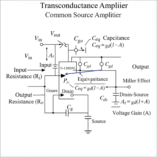
This section details how a common source amplifier can be represented as a trans conductance amplifier, emphasizing the relationship between voltage gain and trans conductance. Various parameters, including output resistance, input resistance, and the role of parasitic capacitances in high-frequency applications are also discussed.
Detailed
In this section, we delve into the concept of the Trans Conductance Amplifier, derived from a common source amplifier configuration. The discussion elucidates how the amplifier can be viewed as a trans conductance amplifier with defined parameters such as voltage gain (A), output resistance (Ro), and input resistance (Ri). The relation between voltage gain and trans conductance (G) is introduced, with G being proportional to the voltage gain with a negative sign. The importance of parasitic capacitances, particularly in high-frequency scenarios, is highlighted, explaining how these can impact performance through the Miller effect. A numerical example is provided to illustrate the calculation of parameters, making practical connections to the design and operation of such amplifiers in analog electronics.
Youtube Videos

Audio Book
Dive deep into the subject with an immersive audiobook experience.
Understanding the Trans Conductance Amplifier
Chapter 1 of 5
🔒 Unlock Audio Chapter
Sign up and enroll to access the full audio experience
Chapter Content
So, the signal at this input port will be always in the form of voltage. On the other hand, the output port at the signal either can be voltage as we are showing here, but then it can be even current also.
Detailed Explanation
A trans conductance amplifier is a type of amplifier where the input is a voltage and the output is a current. This means that when you apply a certain voltage at the input, the amplifier will produce a current at the output based on its trans conductance, which is the ratio of output current to input voltage. The concept is important because it allows us to design amplifiers that can convert voltage signals into current signals that are useful in many applications, like driving loads or interfacing with other electronic components.
Examples & Analogies
Think of the trans conductance amplifier like a water faucet. The voltage input is like the water pressure from the pipes (input voltage). When you turn the faucet (apply voltage), it allows water (current) to flow out, but how much water flows depends on how wide you turn the faucet and the pressure of the water. This relation helps in designing systems where you need to convert a small 'pressure' (voltage) into a 'flow' (current) that can do work, like lighting a bulb.
Input and Output Characteristics
Chapter 2 of 5
🔒 Unlock Audio Chapter
Sign up and enroll to access the full audio experience
Chapter Content
At the input it remains the same namely R, but at the outputs we'll have different model. This is G × v, note that this G it is in incidentally it may be same as the small g that is the trans conductance of the device, but in general need not be the same.
Detailed Explanation
In a trans conductance amplifier, the input is characterized by a resistance, while at the output, we have a different model depicted by a conductance G multiplied by the input voltage v. This trans conductance G represents how effectively the amplifier changes an input voltage into an output current. It's important to note that while in some cases G may equal the intrinsic trans conductance of the device (small g), they can also differ, impacting how the amplifier behaves.
Examples & Analogies
Imagine a traffic system where cars (current) flow through intersections. Here, the intersection's characteristics (input resistance R) decide how many cars can enter at once depending on the flow of incoming cars (voltage). The 'traffic light' (G × v) determines how many cars can pass through as it changes the passage based on the number of incoming cars. Similarly, the relationship between voltage and output current in a trans conductance amplifier depends on these parameters, allowing for controlled output.
Relationship Between Trans Conductance and Voltage Gain
Chapter 3 of 5
🔒 Unlock Audio Chapter
Sign up and enroll to access the full audio experience
Chapter Content
What we will be discussing here is the relationship between output voltage and input voltage. This means that open loop output voltage must match the developed voltage gain.
Detailed Explanation
When working with a trans conductance amplifier, it's essential to understand how the output voltage relates to the input voltage as controlled by the amplifier's gain. The open loop voltage gain A represents how much the amplifier increases the input signal. To accurately assess the performance of the amplifier, this relationship must be established and used to predict how changes in input will affect output. Typically, it involves understanding the device's trans conductance.
Examples & Analogies
Consider a school where the number of students attending a class can vary. If the teacher's effectiveness (gain) can boost learning, then changes in student engagement (input voltage) will lead to changes in overall understanding in the class. Just like in the amplifier where a certain voltage input leads to a proportionate output voltage, the ability of the teacher to teach effectively correlates with the students' performance.
Frequency Response and Practical Considerations
Chapter 4 of 5
🔒 Unlock Audio Chapter
Sign up and enroll to access the full audio experience
Chapter Content
Now, if we consider the high frequency situation; namely if we consider the signal you are feeding here it is in the high frequency range.
Detailed Explanation
When dealing with trans conductance amplifiers in high-frequency situations, several factors come into play, such as parasitic capacitance which can affect performance. At high frequencies, capacitances that were negligible at lower frequencies may become significant, altering both gain and bandwidth of the amplifier. Therefore, engineers must take these effects into account when designing circuits operating at high frequencies.
Examples & Analogies
Think of a water pipe system. At low flow rates, the smoothness of the pipe doesn't matter much, but as you increase the flow (high frequency), any roughness or bends (parasitics) in the pipe becomes significant, causing turbulence and loss of pressure. Similarly, in an amplifier at high frequencies, these unwanted effects can distort signals, thus they must be designed to minimize such impacts.
Conclusion and Applications
Chapter 5 of 5
🔒 Unlock Audio Chapter
Sign up and enroll to access the full audio experience
Chapter Content
In the context of microelectronics and VLSI design where MOSFET transistors are primarily used.
Detailed Explanation
Trans conductance amplifiers play a crucial role in microelectronics, especially for integrating voltage and current signals in circuits. They allow efficient interfacing of various components in VLSI designs, making them essential for modern electronic devices. Understanding their operation is vital for designing circuits that are reliable and efficient at the same time.
Examples & Analogies
Envision a smart city where different devices (like traffic lights, cameras, sensors) need to work together efficiently. Using trans conductance amplifiers in such systems helps manage the interaction between these devices like managing traffic flow based on real-time data, ensuring the systems work harmoniously. This is akin to how modern electronics leverage trans conductance for seamless operations.
Key Concepts
-
Trans Conductance: The relationship between output current and input voltage.
-
Voltage Gain (A): The ratio of output voltage to input voltage.
-
Output Resistance (Ro): Impediment to current flow, affecting load interactions.
-
Input Resistance (Ri): Resistance that affects loading on previous stages.
-
Parasitic Capacitances: Unintended capacitances in circuits impacting high-frequency performance.
-
Miller Effect: Increases the apparent input capacitance due to feedback.
Examples & Applications
An example of a trans conductance amplifier with a trans conductance value of 2 mA/V and a load resistance of 3 kΩ results in a voltage gain of -6.
Incorporating the Miller effect, a parasitic capacitance observed can significantly affect the frequency response of the amplifier at higher frequencies.
Memory Aids
Interactive tools to help you remember key concepts
Rhymes
Trans conductance amplifies flow, input voltage makes the current go!
Stories
In an electronics kingdom, the trans conductance amplifier stood tall, converting voltage to current with unity for all in the circuit hall.
Memory Tools
GIV (Gain, Input resistance, Voltage control) helps you remember the key elements of trans conductance amplifiers.
Acronyms
VoICe
Voltage output is controlled effectively
describes how we view amplifiers.
Flash Cards
Glossary
- Trans Conductance
The ratio of output current to input voltage, denoting how effectively the amplifier can control current.
- Voltage Gain (A)
The ratio of output voltage to input voltage in an amplifier.
- Output Resistance (Ro)
Resistance seen looking into the output of the amplifier, important for load interaction.
- Input Resistance (Ri)
Resistance seen looking into the input of the amplifier, important for preventing loading effects.
- Parasitic Capacitances
Unintentional capacitances in circuit layouts that can influence performance, especially at high frequencies.
- Miller Effect
A phenomenon that causes an increase in input capacitance due to feedback in amplifiers.
Reference links
Supplementary resources to enhance your learning experience.