
Output Resistance
Enroll to start learning
You’ve not yet enrolled in this course. Please enroll for free to listen to audio lessons, classroom podcasts and take practice test.
Interactive Audio Lesson
Listen to a student-teacher conversation explaining the topic in a relatable way.
Understanding Output Resistance
🔒 Unlock Audio Lesson
Sign up and enroll to listen to this audio lesson

Today, we are going to discuss the concept of output resistance in analog amplifiers, specifically in Common Source Amplifiers. Can anyone tell me what output resistance signifies in an amplifier?

Does it represent how much the output voltage can change with a change in output current?
Exactly! Output resistance indicates how an amplifier behaves under load conditions. It affects how much the output voltage will vary when the load connected to the output changes. Let's observe how we can calculate output resistance using small signal analysis.

Can you explain the small signal model again?
Sure! In the small signal model, we simplify the circuit by setting the DC biasing to zero. This helps us focus on just the AC signals. We need to consider the AC signals flowing through the output resistance to analyze the gain of the amplifier. Remember: small signal analysis often involves linear approximations. Here's a mnemonic to remember: 'Small Signals Lead to Big Insights!'
Calculating Output Resistance
🔒 Unlock Audio Lesson
Sign up and enroll to listen to this audio lesson

Now let's delve deeper into calculating output resistance. We connect a hypothetical voltage source at the output to observe the current that results. Who can tell me the relationship between output voltage, current, and resistance?

Isn't it just Ohm's Law? Voltage equals current times resistance?
Correct! When we apply a voltage source, say v_x, the output current i_x is related by the equation v_x = R_out * i_x. In this case, we can define the output resistance R_out as R_out = v_x / i_x. Keep in mind, we assume that all other parameters in our model behave linearly under small signal conditions.

When setting v_x to zero, do we still get output resistance?
Great question! When v_x is applied, it effectively allows us to observe the output impedance based solely on the conditions at that port. It doesn't directly measure 'zero', rather we look at the response of the output to the perturbation caused by v_x.
Practical Implications of Output Resistance
🔒 Unlock Audio Lesson
Sign up and enroll to listen to this audio lesson
Now that we've summarized how to calculate output resistance let's discuss its implications in amplifier design. Why do you think output resistance matters for real-world applications?
I presume it affects how the amplifier interacts with the load?
Correct! High output resistance can lead to significant voltage drop across the load and can affect the overall voltage gain. This is especially true in applications where accurate signal representation is critical.
Are there standard values for output resistance we should aim for?
Typically, in operational amplifiers, lower output resistance is preferred — usually in the range of tens of ohms — to minimize voltage drop when driving different loads. A solid mnemonic to remember this is 'Less Resistance, More Output!', indicating that lower output resistance generally translates to better performance.
Introduction & Overview
Read summaries of the section's main ideas at different levels of detail.
Quick Overview
Standard
The section explores output resistance as one of the key parameters of a Common Source Amplifier, detailing how it can be determined through circuit analysis. It emphasizes the relationship between output resistance, input voltage, and output current, along with its significance in amplifier design.
Detailed
Detailed Summary
The output resistance of a Common Source Amplifier plays a crucial role in its performance. As stated, once the DC conditions are set to zero in the small signal equivalent circuit, the output resistance can be calculated based on the relationship between the output voltage and the output current.
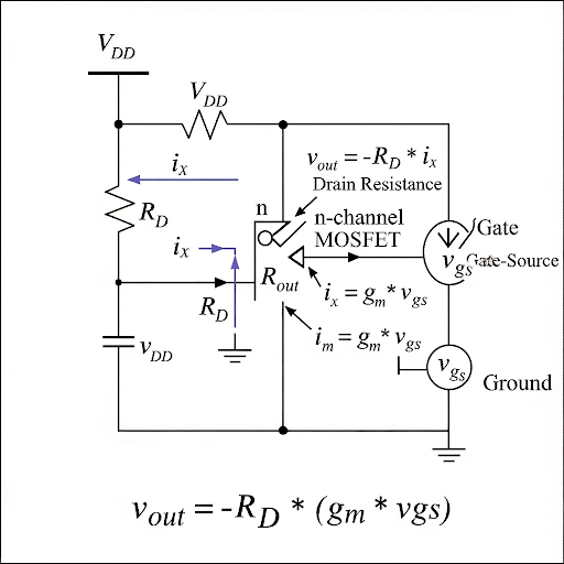
By using Kirchhoff's laws and simplifying the circuit, it's established that the output voltage (v_out) is equal to -R_D * i_x, where R_D is the drain resistance, and i_x is the current flowing through the amplifier. The simplified relationship arrives at:
v_out = -R_D * (g_m * v_gs), where g_m is the transconductance and v_gs is the gate-source voltage.
In addition, the output resistance (R_out) can also be measured independently by applying a voltage source at the output and measuring the resulting current. The notable finding is that the input capacitor and the gate current is zero under small signal conditions, allowing assumptions of the circuit elements for clear calculations of resistance. Overall, the section systematically outlines how output resistance, along with voltage gain, is pivotal in analyzing amplifier characteristics, ultimately leading to considerations for high-frequency effects and gain improvements in circuit design.
Youtube Videos

Audio Book
Dive deep into the subject with an immersive audiobook experience.
Understanding Output Resistance
Chapter 1 of 5
🔒 Unlock Audio Chapter
Sign up and enroll to access the full audio experience
Chapter Content
The second parameter it is the output resistance. So, if you look into this circuit and then if you observe this circuit from outside and if you see what is a corresponding output resistance. So, while we will be doing this as we said that we can connect a signal source here and then we have to make this part equals to 0. So, once you make this is equal to 0, this part it is 0. So, that makes this current it is also 0 and then if you stimulate this output port by say v and then if you observe the corresponding current here as i .
Detailed Explanation
The output resistance of an amplifier is an essential parameter as it defines how much the output voltage can change in response to a change in load current. Here, we imagine connecting a signal source to the circuit being studied. We effectively isolate the output characteristics by setting certain parameters to zero, specifically ensuring that the current flowing through the circuit is minimal, thereby simplifying our analysis.
Examples & Analogies
Think of this like a water faucet. When you turn it off (make the part equals to zero), there’s no water flowing (current). If you ask how much pressure (voltage) you would get when the faucet is open with a certain knob position (output resistance), it is much simpler to predict if you know what happens when the faucet is off.
Calculating Output Voltage
Chapter 2 of 5
🔒 Unlock Audio Chapter
Sign up and enroll to access the full audio experience
Chapter Content
In fact, the current it is only going through this resistance. So, then v and the i relationship you will get is basically v = R × i . So, that gives us the expression of v which is defined as v = R ; so, that is the second parameter we obtained.
Detailed Explanation
To determine the output voltage (v), we utilize Ohm's law, which states that voltage (v) is the product of current (i) times resistance (R). By analyzing the flow of current through the resistance present in the circuit, we can calculate the output voltage. This relationship allows us to define output resistance as a crucial supporting factor in the overall functioning of the amplifier.
Examples & Analogies
Let’s consider a garden hose that constricts flow due to kinks in the hose. If you push water through, the pressure and flow draw a direct connection between the water pressure (voltage) and how hard you push (current). The resistance provided by the kink in the hose simulates output resistance, affecting how effectively water can reach your garden.
Input Resistance Considerations
Chapter 3 of 5
🔒 Unlock Audio Chapter
Sign up and enroll to access the full audio experience
Chapter Content
Now, the third parameter it is; so, at the input port if we see and if you see what is the corresponding resistance here. And, since the circuit here it is open namely the gate current is 0 whether it is large signal or small signal as long as we are not considering the effect of the capacitance from gate to source we can assume that this is equal to 0.
Detailed Explanation
When we look at the input port of the amplifier circuit, we evaluate the resistance observed from this point of view. Since we assume there is no current (open circuit condition), we can simplify our calculations by considering the input resistance to be negligible. Under normal small-signal analysis, we do not consider the influence of capacitance, emphasizing the linearity of the circuit response.
Examples & Analogies
Imagine a door that is kept permanently open (no current). Your ability to interpolate air (current) through this door is clearly minimal, so the resistance against airflow at this door (input resistance) can be considered as effectively zero. In practical terms, this means that when you blow into one side, you won't be met with much opposition.
Synthesizing Parameters into Models
Chapter 4 of 5
🔒 Unlock Audio Chapter
Sign up and enroll to access the full audio experience
Chapter Content
So, what do you obtain here it is A expression of A = – g × R ; R = (R ⫽ R ); it is coming from the bias circuit and then output resistance equal to R . So, that is how the entire circuit you can map into this voltage model.
Detailed Explanation
We combine our previously discussed parameters into a comprehensive model for the amplifier circuit. Here we derive the overall voltage gain (A) of the amplifier, which is associated with the output resistance (represented as R) and the transconductance (g). This mathematical representation is essential for understanding how the amplifier behaves under varying conditions and provides a simplified version of our analysis.
Examples & Analogies
If we consider a classroom with multiple students contributing to a group project (amplifier), the effectiveness of the project can be summarized (the gain) by how well the students (input signals) collaborate and the teaching method applied (parameters R and g). Their combined effect leads to a robust choice in presenting the project findings.
Final Thoughts on Output Resistance
Chapter 5 of 5
🔒 Unlock Audio Chapter
Sign up and enroll to access the full audio experience
Chapter Content
And of course, from outside if we are giving a stimulus say v and then if you are connecting some load here then you can find the corresponding primary input to primary output voltage.
Detailed Explanation
When we connect a load to our amplifier circuit and apply an external signal (v), it affects the output voltage that can be observed. This stress-test scenario helps us evaluate how well the amplifier handles different loads, providing a clearer understanding of practical applications and requirements in real-world settings.
Examples & Analogies
Relate this to how plants react to fertilizers (stimulus) in a garden. If a gardener adds fertilizer (the load) to the soil, it enhances the ability of plants (amplifier) to grow (output voltage). Depending on how much fertilizer is added, the plants will show various levels of growth, exhibiting the amplifier's adaptability and strength in performance.
Key Concepts
-
Output Resistance: The resistance seen at the output of an amplifier affecting how it interacts with a load.
-
Small Signal Equivalent Circuit: A simplified model used to analyze circuits when driven by small AC signals.
-
Voltage Gain: The ratio of the output voltage to the input voltage in an amplifier, often influenced by output resistance.
Examples & Applications
If a Common Source Amplifier has a drain resistance of 3 kΩ and provides a small signal output of 2 mA, its output voltage can be calculated by multiplying the current by the resistance, showing how the output behavior changes with different load conditions.
In practical applications, if an amplifier with high output resistance drives a load with only 1 kΩ resistance, a significant voltage drop may occur across the load, reducing the amplifier’s effective output voltage.
Memory Aids
Interactive tools to help you remember key concepts
Rhymes
When output’s high, keep resistance low; for clear signals, let the current flow!
Stories
Imagine you're a signal trying to flow through an amplifier. If there’s a big wall (high output resistance), you'll struggle to move, and not reach your destination strong enough. But if the wall is low, you glide through smoothly.
Memory Tools
Remember 'GROW' for output resistance: Gains Ruined by Output 'Wattage!'
Acronyms
R.O.A.D. - Resistance Observed as the Amplifier Drives.
Flash Cards
Glossary
- Output Resistance
The resistance looking into the output of an amplifier, determining how the output voltage changes in response to output current variations.
- Small Signal Model
A linear approximation of a nonlinear device (like a transistor) to analyze its behavior in response to small AC signals while ignoring DC bias.
- Transconductance (g_m)
The ratio of the output current to the input voltage in an amplifier, measured in siemens, representing the amplifier's efficiency.
Reference links
Supplementary resources to enhance your learning experience.