
Input Resistance
Enroll to start learning
You’ve not yet enrolled in this course. Please enroll for free to listen to audio lessons, classroom podcasts and take practice test.
Interactive Audio Lesson
Listen to a student-teacher conversation explaining the topic in a relatable way.
Understanding Input Resistance
🔒 Unlock Audio Lesson
Sign up and enroll to listen to this audio lesson

Today, let's talk about input resistance. Can anyone tell me what input resistance means in the context of an amplifier?

Isn't it the resistance seen by the input source?
Exactly! It's the resistance that the amplifier presents to the input source. Higher input resistance is generally desirable.

Why is a higher input resistance better?
A higher input resistance reduces the loading effect on the previous stage, which means less signal loss. Remember 'HIRC'—Higher Input Resistance is Critical!

What exactly affects input resistance?
Good question! Input resistance is affected by component values and configuration. We typically model it with resistors in parallel at the input.

So, if I have R1 and R2 connected to ground at the input, how do we calculate it?
You'd use the formula R_in = R1 || R2. This means R1 in parallel with R2. Let's practice this calculation.
Calculating Input Resistance
🔒 Unlock Audio Lesson
Sign up and enroll to listen to this audio lesson

Let's say we have R1 as 10 kΩ and R2 as 20 kΩ. What is R_in?
I think we calculate it as 1 / ((1/R1) + (1/R2)).
Correct! Let's solve it together. What do you get?
It should be around 6.67 kΩ.
Perfect! Understanding this calculation is crucial since input resistance affects the amplifier's performance in real applications. Who can remind me why this is important?
It helps maintain signal integrity and minimizes distortion from loading.
Exactly! It helps to ensure we get an accurate representation of the input signal.
Significance of Input Resistance
🔒 Unlock Audio Lesson
Sign up and enroll to listen to this audio lesson
Why do you think input resistance is critical when designing amplifiers?
I suppose it prevents loss of signal at the input stage?
That's right! It preserves the signal's voltage level and improves accuracy. Think of it this way: a high input resistance means less current drawn from the previous circuit.
What kind of applications benefit most from this?
Any sensitive applications, like sensors or audio amplifiers. These require fidelity in signal transmission, so input resistance matters significantly.
Could lower input resistance ever be advantageous?
Lower input resistance could provide better stability in certain configurations, but it generally degrades performance. Remember: R_in ↗ = Performance ↗.
Introduction & Overview
Read summaries of the section's main ideas at different levels of detail.
Quick Overview
Standard
The section details the theory behind input resistance in Common Source Amplifiers. It outlines how to calculate the input resistance based on different configurations and highlights its importance in circuit performance.
Detailed
Input Resistance in Common Source Amplifiers
This section focuses on the input resistance characteristic of Common Source Amplifiers, which play a crucial role in defining the overall performance of electronic circuits. Input resistance (R_in) is the resistance that the amplifier presents to the input signal source. For the Common Source configuration, the gate current is typically assumed to be zero, allowing the input resistance to be calculated based on the resistive and capacitive elements connected at the gate.
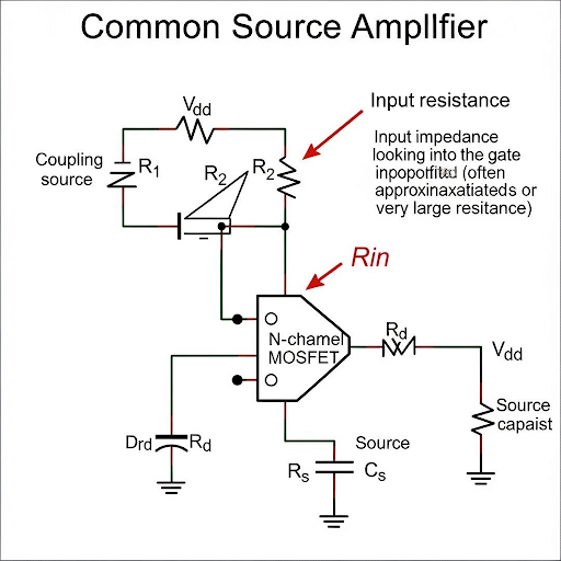
The section discusses the determination of input resistance through small signal analysis. In the input port configuration, the calculation uses the formula R_in = R1 || R2, where R1 and R2 are resistances connected to ground. The relationship emphasizes how input resistance affects the signal integrity and loading effects. It is emphasized that a high input resistance is desirable to ensure minimal loading on the previous circuit stage.
Various practical scenarios and numerical examples are included to illustrate how to derive the input resistance from the small signal model, the implications of low or high input resistance, and how these values help in designing efficient amplifiers suited for specific applications.
Youtube Videos

Audio Book
Dive deep into the subject with an immersive audiobook experience.
Understanding Input Resistance at the Input Port
Chapter 1 of 3
🔒 Unlock Audio Chapter
Sign up and enroll to access the full audio experience
Chapter Content
Now, the third parameter it is; so, at the input port if we see and if you see what is the corresponding resistance here. And, since the circuit here it is open namely the gate current is 0 whether it is large signal or small signal as long as we are not considering the effect of the capacitance from gate to source we can assume that this is equal to 0.
Detailed Explanation
In this chunk, we are discussing the input resistance of the amplifier at its input port. The input port is significant because it is where the input signal is applied. In the case of the Common Source Amplifier, the gate current is essentially zero, meaning that no current flows into the gate of the MOSFET during operation. Because of this, we can simplify our calculations by assuming that the gate acts like an open circuit, leading us to conclude that the input resistance seen by the signal source is very high, often treated as infinite for practical purposes.
Examples & Analogies
Imagine a water pipe system where you are trying to pour water into a large tank (the input port). If the tank is sealed and no water can escape, then you can pour in as much water as you want, and it will take it without any resistance. Similarly, the high input resistance means that the amplifier draws negligible current from the input, allowing the input signal to flow into the circuit without significant loss.
Calculating Input Resistance
Chapter 2 of 3
🔒 Unlock Audio Chapter
Sign up and enroll to access the full audio experience
Chapter Content
So, if we again stimulate this port by say v and whatever the current we observe let you say that this is i. And, this is incidentally it is the current flowing through this R and R. In other words, we can say that i × (R1 || R2) because this is connected to AC ground, this is anyway it is ground. So, that is why that makes this R1 and R2 coming parallel while this is current i flowing.
Detailed Explanation
In this section, we derive an expression for the input resistance. If we apply a small signal voltage, denoted by 'v', to the input, we can measure the resulting current 'i'. The resistances R1 and R2 are in parallel due to how they connect to the AC ground, meaning the combined effect on the input signal is a parallel arrangement. We can represent this relationship mathematically as i = v / (R1 || R2), where || denotes the parallel combination of R1 and R2. Therefore, the input resistance (R_in) can be represented as R_in = v / i = R1 || R2.
Examples & Analogies
Think about two parallel roads leading to a parking lot. If you want to park a car, you have the option of using either road. The more roads (or resistors in this case), the easier it is for cars (current) to flow into the parking lot (input port). Similarly, having resistors in parallel means the circuit allows more input signal to come through, effectively lowering the total resistance and making it easier for the input current to flow.
Mapping Input Resistance in Voltage Model
Chapter 3 of 3
🔒 Unlock Audio Chapter
Sign up and enroll to access the full audio experience
Chapter Content
So, what do you obtain here it is A expression of A = -g_m × R; R = (R1 || R2); it is coming from the bias circuit and then output resistance equal to RD. So, that is how the entire circuit you can map into this voltage model.
Detailed Explanation
In this chunk, we simplify the analysis by mapping the input resistance and understanding its impact on the overall amplifier behavior. The gain 'A' of the amplifier can be expressed as A = -g_m × R_D, where g_m is the transconductance and R_D is the output resistance of the circuit. The important takeaway is that we have effectively combined the input resistance from previous calculations with the output resistance to create a comprehensive model that helps us understand the amplifier's performance parameters.
Examples & Analogies
Imagine adjusting the settings on an audio amplifier. When you set the bass and treble levels (representing R1 and R2), you enhance or reduce certain frequencies. In the same way, tuning the input resistance and output resistance allows the audio amplifier to optimize sound quality and amplification characteristics. The combined effort of these resistances allows for improved sound output from the amplifier, just as it helps optimize signal handling in a circuit.
Key Concepts
-
Input Resistance: The effective resistance seen by the input signal source.
-
Signal Integrity: Maintaining the quality of the signal while passing through components.
-
Loading Effect: The impact of parallel resistance on signal strength.
-
Voltage Division: How resistors can be used to segment input voltages effectively.
Examples & Applications
Calculating the input resistance of a circuit with a 10 kΩ and a 20 kΩ resistor in parallel.
Analyzing the impact of high input resistance in a sensor application.
Memory Aids
Interactive tools to help you remember key concepts
Rhymes
When current flows and resistors play, Higher input resistance is the best way.
Stories
Imagine a tiny bridge where the ants (signal) cross easily when the bridge (input resistance) is wide enough.
Memory Tools
Use 'RISK'—R_for resistance, I_for integrity, S_for signal, K_for keep it high.
Acronyms
INPUT—I for Integrity, N for No load, P for Preserve voltages, U for Utilize correctly, T for Tight design.
Flash Cards
Glossary
- Input Resistance
The resistance that an amplifier presents to its input signal source, affecting signal transfer and loading effects.
- Signal Integrity
The preservation of the input signal quality as it propagates through the circuit.
- Loading Effect
The reduction in signal amplitude that occurs when a component draws current from the circuit it is connected to.
- Voltage Divider
A configuration using resistors to divide input voltage into smaller voltages.
- Fidelity
The degree to which the output signal accurately represents the input signal.
Reference links
Supplementary resources to enhance your learning experience.