
Circuit Analysis
Enroll to start learning
You’ve not yet enrolled in this course. Please enroll for free to listen to audio lessons, classroom podcasts and take practice test.
Interactive Audio Lesson
Listen to a student-teacher conversation explaining the topic in a relatable way.
Overview of Common Emitter Amplifiers
🔒 Unlock Audio Lesson
Sign up and enroll to listen to this audio lesson

Today, we'll discuss common emitter amplifiers and dive deeper into their frequency response. Can anyone remind me what the general function of a common emitter amplifier is?

Isn't it used to amplify voltage signals?
Exactly, it's designed to amplify voltage inputs. Remember, we denote voltage gain as A. The relationship is crucial when analyzing the circuit. Now, what do we recall about the self-bias configuration?

It uses resistors in the emitter circuit to stabilize the operating point, right?
Correct! Emitter resistors help in stabilizing the operating point. Let's also note the significance of capacitive coupling in our frequency response analysis.
Frequency Response
🔒 Unlock Audio Lesson
Sign up and enroll to listen to this audio lesson

When we analyze frequency response, we consider both the high-pass and low-pass characteristics. Can anyone explain what we mean by cutoff frequency?

It's the frequency at which the output signal power drops to half of the input signal power?
Great answer! The cutoff frequency is indeed where the response begins to roll off. How do we determine these cutoff frequencies in practical circuits?

We can use the component values for capacitors and resistors to calculate them, right?
Absolutely! That’s why understanding the numerical analysis is crucial. Let's review how to derive those values.
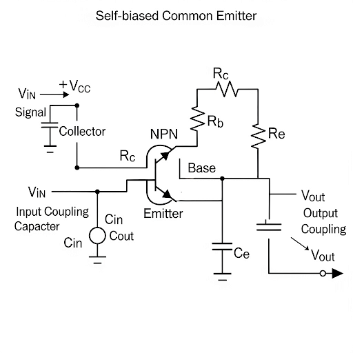
Self-Biased Common Emitter Amplifier
🔒 Unlock Audio Lesson
Sign up and enroll to listen to this audio lesson
Now, moving on to the self-biased common emitter amplifier. What is the structure we typically use for this amplifier?
It involves resistors at the base, which generate a DC voltage and utilizes an emitter resistor for stability.
Exactly right! Now, can anyone describe how we determine input resistance and voltage gain for this configuration?
We calculate the input resistance by considering the resistors in parallel along with the transistor's intrinsic resistance.
Yes, and remember the formula R_in = R1 || R2, alongside the contributions from the transistor! This leads us to our voltage gain expression.
Numerical Examples
🔒 Unlock Audio Lesson
Sign up and enroll to listen to this audio lesson
Let’s work on a numerical example where we need to design a self-biased CE amplifier. What is our first step?
We need to establish our desired cutoff frequencies!
Right! Based on those frequencies, we can iterate through the formulas to find capacitance and resistance values. Let’s compute an example together.
So we’ll plug our values into the voltage gain and resistance formulas?
Exactly! Let’s see what configurations yield the response we expect.
Conclusion and Review
🔒 Unlock Audio Lesson
Sign up and enroll to listen to this audio lesson
To conclude, we have explored the self-biased common emitter amplifier and calculated its frequency response. Can anyone summarize the main components we need for analyzing such a circuit?
We primarily look at the coupling capacitors, resistors for biasing, and those equations for gain and resistance.
Very well summarized! Remember, understanding these concepts will be fundamental for your future projects and analyses.
Introduction & Overview
Read summaries of the section's main ideas at different levels of detail.
Quick Overview
Standard
In this section, key concepts related to the frequency response of common emitter and common source amplifiers are discussed. The emphasis is placed on the self-biased common emitter amplifier, including its numerical analysis and the derivation of input/output resistance and voltage gain.
Detailed
Circuit Analysis Summary
This section delves into the frequency response of common emitter (CE) and common source (CS) amplifiers, with a distinct focus on the self-biased common emitter amplifier. The discussion begins with a brief recapitulation of the core concepts and moves towards numerical examples that showcase how to determine component values based on provided cutoff frequencies. Throughout the analysis, voltage gain calculations, input/output resistance derivations, and the significance of capacitive components in circuit design are emphasized, preparing students for practical applications in circuit analysis.
Youtube Videos

Audio Book
Dive deep into the subject with an immersive audiobook experience.
Introduction to Self-Biased Common Emitter Amplifier
Chapter 1 of 6
🔒 Unlock Audio Chapter
Sign up and enroll to access the full audio experience
Chapter Content
So, we are going to start with the common emitter amplifier with self-biased and its corresponding circuit analysis.
Detailed Explanation
This chunk introduces the focus of the lecture, which is the self-biased common emitter amplifier. In this type of amplifier, the biasing is achieved using a feedback mechanism that stabilizes the operating point against variations. This is different from fixed biasing where a constant voltage source is used to set the operating point.
Examples & Analogies
Think of this amplifier like a thermostat that automatically adjusts the temperature in your home. Just as the thermostat sensors detect changes in temperature and adjust the heating or cooling accordingly, a self-biased amplifier adjusts its biasing to maintain optimal performance despite fluctuations in input signal or temperature.
Recap of Previous Concepts
Chapter 2 of 6
🔒 Unlock Audio Chapter
Sign up and enroll to access the full audio experience
Chapter Content
So, again we are since we are going to start from the previous topic where you have left, so we need to just recapitulate some part of it, particularly the R-C circuit and C-R circuit analysis.
Detailed Explanation
Before delving into new topics, it's important to recall previous lessons on R-C and C-R circuits. These analyses are foundational as they help us understand how frequency response behaves in amplifiers. The R-C circuit typically affects the high frequency response while the C-R circuit impacts the low frequency response.
Examples & Analogies
Imagine preparing a recipe that requires you to remember some key steps from a previous experience. Just as recalling those steps helps you make the dish successfully, reviewing past concepts helps students effectively build upon their knowledge of circuit analysis.
Overview of Circuit Components and Frequency Response
Chapter 3 of 6
🔒 Unlock Audio Chapter
Sign up and enroll to access the full audio experience
Chapter Content
The overall frequency response it is having three parts. So, is one is the frequency response of the C-R part and then frequency response of the main amplifier part and then followed by frequency response of the R-C circuit.
Detailed Explanation
The frequency response of a self-biased common emitter amplifier is composed of three key components: the C-R part, which influences how the circuit reacts at high frequencies; the main amplifier part, which defines the gain; and the R-C circuit, which affects low frequency behavior. Each part plays a role in determining the overall frequency response of the circuit.
Examples & Analogies
Consider a car navigating through different types of roads: high-speed highways, city streets, and rural paths. Each type of road represents a different frequency response portion, each affecting the car's speed and handling characteristics. Similarly, these circuit components govern how the amplifier responds to varying frequencies.
Analysis of the Core Circuit
Chapter 4 of 6
🔒 Unlock Audio Chapter
Sign up and enroll to access the full audio experience
Chapter Content
Let us see what is the analysis of this core portion, and out of this what we are looking for it is the voltage gain whatever A and then R and then R.
Detailed Explanation
In analyzing the core portion of the self-biased common emitter amplifier, we seek to determine key parameters such as voltage gain, input resistance, and output resistance. Understanding these parameters is crucial since they dictate the amplifier's overall performance and characteristics.
Examples & Analogies
Think of the amplifier as a public speaker at an event. The voltage gain is like the speaker's volume—how loud they can project their voice and reach the audience. Input and output resistance are akin to the acoustics of the room, which either amplifies the speaker's voice or absorbs it, affecting overall performance.
Deriving Voltage Gain
Chapter 5 of 6
🔒 Unlock Audio Chapter
Sign up and enroll to access the full audio experience
Chapter Content
Now, what you are doing? That input we are giving at the base node and with respect to ground, but then emitter of the transistor it is not connected to ground rather it is connected to ground through this R as a result this v and v they are not equal.
Detailed Explanation
This chunk explains how the input voltage is introduced at the base of the transistor, while the emitter is connected to ground through a resistor. This unique connection leads to a situation where the input voltage (v) and emitter voltage (v_e) are not equal due to the voltage drop across the emitter resistor caused by the current flowing through it. This relationship is crucial for calculating the voltage gain of the amplifier.
Examples & Analogies
Imagine if a musician has a microphone (input voltage) but is standing on a stage that’s elevated (emitter connection). The musician’s voice reaches the audience (output) differently than if they were standing at ground level, due to this elevation and distance, similar to how the voltages behave in this circuit.
Understanding Input and Output Resistance
Chapter 6 of 6
🔒 Unlock Audio Chapter
Sign up and enroll to access the full audio experience
Chapter Content
So, to summarize, so what we are obtaining here it is this circuit, this circuit is having voltage gain of A and then input resistance it is R ⫽ R and then r + R (1 + β).
Detailed Explanation
By summarizing the outcomes of the analysis, we found that the circuit has a specific voltage gain and input resistance. The input resistance depends on the resistances within the circuit and the transistor's current gain (β), indicating how much input impedance the amplifier presents to the source signal.
Examples & Analogies
Consider a sponge soaking up water. The voltage gain is like how much water the sponge can hold, while the input resistance tells you how quickly the sponge can absorb water. If the sponge is too tough (high resistance), it won’t absorb water efficiently. Similarly, the amplifier’s resistances impact its response to input signals.
Key Concepts
-
Voltage Gain: The ratio of output voltage to input voltage, important for assessing amplifier effectiveness.
-
Cutoff Frequencies: Key frequencies that define the bandwidth of the amplifier, separating amplification from attenuation.
-
Input/Output Resistance: Determines how the amplifier interfaces with other circuits and impacts performance.
-
Self-Biasing: A method to stabilize an amplifier's operating point without needing external biasing.
-
Frequency Response: Characterizes how the output changes relative to a range of input frequencies.
Examples & Applications
Designing a self-biased common emitter amplifier for a specific gain and cutoff frequency.
Analyzing frequency response by simulating a common emitter amplifier with various capacitor and resistor values.
Memory Aids
Interactive tools to help you remember key concepts
Rhymes
Cutoff frequency, don't let it be low, keep the gain high, let the signals flow.
Stories
Imagine a lone amplifier in a bustling circuit town, it needs stability, a self-biasing crown!
Memory Tools
R-I-G-H-T: Remember Input-Resistance, Gain, High-pass and Transistor!
Acronyms
CEG – Common Emitter Gain
Three components we always count for gain.
Flash Cards
Glossary
- Common Emitter Amplifier
A type of amplifier configuration that provides significant voltage gain and is used widely in analog circuits.
- Selfbiasing
A biasing method that uses resistors to stabilize the operating point without the need for external bias voltages.
- Cutoff Frequency
The frequency at which the output signal power falls to half of the input signal power, determining the bandwidth of the amplifier.
- Input Resistance
The resistance seen by the source connected to the input of the amplifier circuit.
- Voltage Gain
The ratio of output voltage to input voltage in an amplifier, typically expressed in decibels (dB).
Reference links
Supplementary resources to enhance your learning experience.