
Recapitulation of Fixed Bias Circuit
Enroll to start learning
You’ve not yet enrolled in this course. Please enroll for free to listen to audio lessons, classroom podcasts and take practice test.
Interactive Audio Lesson
Listen to a student-teacher conversation explaining the topic in a relatable way.
Introduction to Fixed Bias Circuit
🔒 Unlock Audio Lesson
Sign up and enroll to listen to this audio lesson

Welcome, everyone! Today we are going to recap the fixed bias circuit of the common emitter amplifier. Can anyone tell me the fundamentals of a fixed bias configuration?

I think it uses a resistor connected to the base of the transistor to set the bias current?
Exactly! We apply a voltage divider network to establish the base voltage, which in turn sets the operating point of the transistor.

What’s the advantage of this method?
Good question! The fixed bias circuit is simple and cost-effective for low-frequency applications.
Remember, for a quick memory aid, think 'Bias Takes Charge' if you are thinking of fixed bias setting the base voltage!
Frequency Response Analysis
🔒 Unlock Audio Lesson
Sign up and enroll to listen to this audio lesson

Now, let’s discuss the frequency response of our fixed bias common emitter amplifier. Why is this frequency response important?

Isn’t it crucial for understanding how the amplifier behaves with different frequencies?
Exactly! The frequency response shows us the gain of the amplifier varies over different frequencies.

What are the three main parts of the frequency response?
Great question! We analyze it in three parts: the high-pass characteristic of the C-R circuit, the constant gain from the amplifier itself, and the low-pass characteristic of the R-C circuit.
As a mnemonic, remember 'Three C's' – Cutoff, Constant, and Combination!
Key Parameters Calculation
🔒 Unlock Audio Lesson
Sign up and enroll to listen to this audio lesson
Now, let's figure out how to compute the voltage gain of our fixed bias common emitter amplifier. Who can share what factors we need?
We need to look at the resistances, right? Like R_E and R_C?
Correct! The gain formula will incorporate these resistance values and the transistor's current gain, β.
And what about the input and output resistances?
Excellent! Input resistance is influenced by R and also the transistor’s parameters. Let's derive these expressions together.
To promote retention, think of 'Gain Goes Forward' for remembering the gain impacts!
Introduction & Overview
Read summaries of the section's main ideas at different levels of detail.
Quick Overview
Standard
In this section, we recall the fixed bias configuration of the common emitter amplifier, focusing on the circuit's frequency response and its components. Key aspects such as input/output resistance, gain calculations, and how to analyze the combined frequency response of the amplifier with associated RC and CR networks are discussed.
Detailed
In this section, we explore the fixed bias circuit of a common emitter amplifier, placed in the context of its frequency response analysis. The section begins by recapping the fundamental circuit structures, introducing R-C circuits and C-R circuits. It establishes the parameters for circuit analysis, including voltage gain, input and output resistance. Notably, it emphasizes the significance of the frequency response characteristics when cascading various components in the amplifier setup. A transition is made to relate these insights to the self-biased common emitter amplifier in subsequent discussions.
Youtube Videos

Audio Book
Dive deep into the subject with an immersive audiobook experience.
Overview of Fixed Bias Circuit
Chapter 1 of 4
🔒 Unlock Audio Chapter
Sign up and enroll to access the full audio experience
Chapter Content
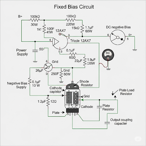
In case, if you recall the fixed bias circuit where this is the circuit diagram given here, which is having coupling capacitor here C1 and C signal coupling capacitor and then we have drawn the small signal equivalent circuit of the amplifier which is basically the core part.
Detailed Explanation
This chunk introduces the fixed bias circuit, highlighting its components such as coupling capacitors. The circuit diagram is not provided here, but the description gives an idea about how the capacitors are positioned within the amplifier. Coupling capacitors (C1 and C2) are crucial as they allow AC signals to pass while blocking DC components, ensuring that only the intended signals reach the amplifier core.
Examples & Analogies
Think of coupling capacitors like a filter in a water system. Just as a water filter allows only clean water to flow through while trapping impurities, the coupling capacitors let AC signals pass and block any unwanted DC voltage.
Input and Output Resistance
Chapter 2 of 4
🔒 Unlock Audio Chapter
Sign up and enroll to access the full audio experience
Chapter Content
On the other hand output side, we are having output resistance of this circuit which is equals to R, and R it was R = r and then it was having the gain which it was g × R.
Detailed Explanation
This chunk explains the output resistance and gain of the amplifier. The output resistance is denoted as R, which plays a key role in how the amplifier interacts with the load. The gain, presented as the product of g (transconductance) and R (output resistance), indicates how much the input signal is amplified. Understanding these parameters is vital for analyzing amplifier performance.
Examples & Analogies
Imagine a speaker amplifier where the output resistance (R) is like the capacity of a hosepipe. The bigger the hose, the more water (or signal) it can push out without losing pressure. The gain can be likened to the height difference in a waterfall; a taller drop (higher gain) means more powerful water flow (signal amplification).
Small Signal Equivalent Circuit
Chapter 3 of 4
🔒 Unlock Audio Chapter
Sign up and enroll to access the full audio experience
Chapter Content
This circuit frequency response of this circuit, it was obtained by considering its small signal equivalent circuit and then further from this it has been mapped onto on this generalized C-R amplifier R-C circuit and then we obtain the corresponding frequency response of this amplifier.
Detailed Explanation
This portion discusses how the small signal equivalent circuit of the fixed bias circuit is analyzed. By simplifying the circuit to consider only small variations around a bias point, it becomes easier to derive the frequency response, which shows how the amplifier behaves at different frequencies. The transformation into a generalized C-R/R-C circuit helps simplify calculations and predictions about performance.
Examples & Analogies
Think of a small signal equivalent circuit as using a mini-version of a roller coaster to predict what a full-sized ride would be like. By testing the mini-coaster, you gain insights on speed and loops that apply to the big ride, just like we analyze small signals to predict amplifier behavior.
Conclusion and Next Steps
Chapter 4 of 4
🔒 Unlock Audio Chapter
Sign up and enroll to access the full audio experience
Chapter Content
So, that is what we have discussed in the previous day, now we are going to discuss about CE amplifier having self-biased arrangement.
Detailed Explanation
This concluding chunk indicates a transition from revisting the fixed bias circuit to introducing a new topic: the self-biased CE amplifier. Understanding fixed bias circuits is crucial as it sets the foundational knowledge for exploring more complex circuits, like self-biased configurations that may address some limitations of fixed bias circuits.
Examples & Analogies
Imagine you've learned how to bake a basic cake (fixed bias). Now, you're ready to learn how to bake a more advanced recipe like a self-sufficient soufflé that helps retain its fluffiness even when things change. Each learning step builds upon the last, preparing you for more complex tasks in circuit design.
Key Concepts
-
Fixed Bias Configuration: A method to bias a transistor using a resistor connected to the base.
-
Frequency Response: The output behavior of an amplifier across different frequencies.
-
Voltage Gain: The ratio of amplifier's output voltage to input voltage, important for determining amplification capacity.
Examples & Applications
Calculating the frequency response for different values of coupling capacitors in the fixed bias configuration.
Analyzing how varying R_E affects the input and output resistances of a common emitter amplifier.
Memory Aids
Interactive tools to help you remember key concepts
Rhymes
Gain in the brain, with R and C; the circuits work like poetry!
Stories
Imagine a stable boat (fixed bias) floating on a calm lake (frequency response), where each wave (frequency) changes the view, but the boat stays steady.
Memory Tools
Use the acronym 'GIRLS' to remember: Gain, Input Resistance, Resistance, Load, Stability in circuits.
Acronyms
CAPS to remember frequency response
for Cutoff
for Analysis
for Performance
for Stability.
Flash Cards
Glossary
- Common Emitter Amplifier
A type of amplifier where the input is applied to the emitter and output is taken from the collector, providing voltage gain.
- Fixed Bias
A method of biasing a transistor where a resistor is connected to the base to provide a stable voltage.
- Frequency Response
The measure of an amplifier's output spectrum as a function of frequency.
- Cutoff Frequency
The frequency at which the output signal power is reduced to half its maximum value.
- Voltage Gain
The ratio of output voltage to input voltage for an amplifier circuit.
Reference links
Supplementary resources to enhance your learning experience.