
Overall Frequency Response
Enroll to start learning
You’ve not yet enrolled in this course. Please enroll for free to listen to audio lessons, classroom podcasts and take practice test.
Interactive Audio Lesson
Listen to a student-teacher conversation explaining the topic in a relatable way.
Frequency Response of Common Emitter Amplifier
🔒 Unlock Audio Lesson
Sign up and enroll to listen to this audio lesson

Today, we’re delving into the frequency response of the common emitter amplifier, especially focusing on self-bias arrangements. Can anyone tell me what a self-biased configuration means?

Is it where the biasing is done through a resistor linked to the emitter?
Exactly! Self-biasing typically employs an emitter resistor which helps stabilize the operating point. Let's explore how the self-biased arrangement influences input and output resistances. What do you think would happen to input resistance in this case?

It might increase due to the negative feedback from the emitter resistor, right?
Spot on! This feedback effect indeed increases input resistance, which is essential for frequency response analysis. Let’s summarize this interaction: the self-bias impacts both stability and frequency response.
Analyzing Frequency Components
🔒 Unlock Audio Lesson
Sign up and enroll to listen to this audio lesson

Now, let’s shift gears and focus on cutoff frequencies. Who can define what a cutoff frequency signifies in an amplifier circuit?

Is it the frequency at which the output power falls below half of the maximum power?
Very well put! In our analysis, the lower cutoff frequency often arises from coupling capacitors, while the upper cutoff is associated with bypass capacitors. Can someone explain the relationship between these frequencies and components?

The coupling capacitors affect the lower frequency cutoff, and the bypass capacitor can significantly influence the upper cutoff.
Exactly! Understanding these relationships helps create efficient amplifiers. Let’s summarize: coupling caps impact low-frequency response, while bypass caps shape the high-frequency end.
Circuit Analysis Application
🔒 Unlock Audio Lesson
Sign up and enroll to listen to this audio lesson
We’ve discussed the theory; now, let’s look at practical applications. How do we determine the values of capacitors in a circuit given specific cutoff frequencies?
We can use standard formulas derived from our earlier analysis.
Precisely! By applying our knowledge of frequency response, we can derive the necessary capacitor values for different frequencies. What if the lower cutoff frequency is specified—what would you do next?
I would calculate the appropriate coupling capacitor based on that frequency.
Great! Understanding these calculations will facilitate efficient amplifier design. Recapping, we used cutoff frequencies to derive capacitor values.
Introduction & Overview
Read summaries of the section's main ideas at different levels of detail.
Quick Overview
Standard
The section discusses the frequency response of common emitter amplifiers, elaborating on self-biased configurations, circuit analysis, and numerical examples. It emphasizes how to determine the values of capacitive components based on lower and upper cutoff frequencies, illustrating key concepts of frequency response in amplifiers.
Detailed
In this section of the Analog Electronic Circuits lecture, the focus is on studying the frequency response of common emitter (CE) amplifiers, particularly in self-biased arrangements. The instructor recaps previous discussions on frequency response, specifically regarding common emitter and common source amplifiers, and then transitions into self-biased configurations. Key concepts include the analysis of input and output resistances, voltage gain, and the relationship between different frequency response components like high-pass and low-pass characteristics. Furthermore, the section concludes with numerically grounded approaches to determine capacitor values for designed cutoff frequencies, thereby enhancing understanding of design guidelines in amplifier circuits. The summary effectively captures the critical aspects that will aid in constructing and analyzing amplifier frequency responses comprehensively.
Youtube Videos

Audio Book
Dive deep into the subject with an immersive audiobook experience.
Introduction to Frequency Response
Chapter 1 of 4
🔒 Unlock Audio Chapter
Sign up and enroll to access the full audio experience
Chapter Content
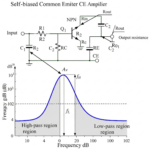
The overall frequency response starts from the primary input to the primary output. We obtain the frequency response in three parts, which are: the frequency response of the C-R circuit, the frequency response of the main amplifier part, and the frequency response of the R-C circuit.
Detailed Explanation
The concept of overall frequency response refers to how a circuit responds to different frequencies of input signals. It is essential for understanding how circuits amplify signals across various frequency ranges. Usually, the overall response is divided into three primary sections: the input section (C-R circuit), the amplification section (main amplifier), and the output section (R-C circuit). Each of these parts contributes differently to how the circuit behaves when different frequencies are applied.
Examples & Analogies
Think of a frequency response as how a music playlist sounds at different volumes—some songs (frequencies) might sound great at a quiet volume but be drowned out at higher volumes. Similarly, different parts of a circuit might perform better or worse depending on the input frequency.
Understanding Circuit Components
Chapter 2 of 4
🔒 Unlock Audio Chapter
Sign up and enroll to access the full audio experience
Chapter Content
Each part of the frequency response has specific characteristics: the C-R circuit has a high pass characteristic with a cutoff frequency, while the main amplifier gives a constant gain, and the R-C circuit demonstrates a low pass characteristic.
Detailed Explanation
The high pass characteristic of the C-R circuit allows it to pass higher frequencies while blocking lower ones—this is crucial for filtering out unwanted noise. The main amplifier part maintains a constant gain over a specific frequency range, which ensures that the amplification of signals does not vary greatly. Finally, the R-C circuit acts as a low pass filter, allowing lower frequencies to pass while attenuating higher frequencies. Understanding how these sections operate together provides insight into designing effective amplifiers.
Examples & Analogies
Imagine a pair of headphones that have a built-in filter to enhance bass sounds (low pass) but reduce treble sounds (high pass). This is similar to how these circuits filter and amplify different frequencies of audio signals to produce a desired sound.
Using the Overall Frequency Response in Design
Chapter 3 of 4
🔒 Unlock Audio Chapter
Sign up and enroll to access the full audio experience
Chapter Content
The overall frequency response can inform how to select components like coupling capacitors and load capacitances in circuit design.
Detailed Explanation
By analyzing the overall frequency response, engineers can determine the appropriate values for various circuit components. For example, if the cutoff frequencies dictate a need for specific coupling capacitances, designers can select capacitors that meet these needs to optimize circuit performance. This is part of the design guidelines that help in achieving efficiency and effectiveness in the overall amplifier design.
Examples & Analogies
Consider tuning a guitar; just as a musician adjusts the tension in the strings to achieve the correct pitch (optimal frequency), engineers adjust capacitors and resistors based on the desired response they want from their circuits. Their goal is to ensure the 'sound' of the circuit aligns with the intended use.
Visualizing Frequency Response
Chapter 4 of 4
🔒 Unlock Audio Chapter
Sign up and enroll to access the full audio experience
Chapter Content
When combining the frequency responses of all parts, one can visualize the behavior of the entire system, illustrating how frequency response shifts with different components and arrangement.
Detailed Explanation
Visualizing the overall frequency response helps to understand how the entire circuit operates across the frequency spectrum. Graphs can illustrate how gain varies with frequency and where the cutoff frequencies lie. This visualization is a powerful tool in circuit analysis, allowing engineers to see at a glance where improvements may be needed or how different configurations might affect performance.
Examples & Analogies
Think of visualizing frequency response as looking at a weather forecast. Just as graphs show temperature changes throughout the day, frequency response graphs show how an amplifier's performance changes across different frequencies, helping engineers make informed decisions about circuit design.
Key Concepts
-
Self-Biased Configuration: Configuring a transistor amplifier with an emitter resistor for stability and frequency response.
-
Cutoff Frequencies: The frequencies that determine the bandwidth of the amplifier, impacting overall performance.
-
Voltage Gain: The ratio of output voltage to input voltage, pivotal for understanding amplifier efficiency.
Examples & Applications
When designing a common emitter amplifier with a lower cutoff frequency of 20 Hz, the coupling capacitor can be calculated to allow signals above this threshold while blocking unwanted DC.
For a self-biased CE amplifier, using a bypass capacitor significantly lowers the effective resistance at high frequencies, leading to higher voltage gain.
Memory Aids
Interactive tools to help you remember key concepts
Rhymes
If gain you chase, an emitter's grace, stabilizes your base!
Stories
Imagine a cautious driver (the emitter resistor) steering a car (the amplifier) through unpredictable roads (current changes). The driver's careful adjustments keep the journey steady, representing the stability offered in a self-biased amplifier.
Memory Tools
RC for coupling, BC for bypass, remember these to make your signals amass!
Acronyms
CAP - Coupling and Bypass for Amplifier Performance.
Flash Cards
Glossary
- Common Emitter Amplifier
A type of amplifier configuration that uses a transistor whose emitter is common to both the input and output circuits.
- SelfBiased Configuration
A biasing method that employs resistor feedback from the emitter to maintain stable transistor operation.
- Cutoff Frequency
The frequency at which the output signal power drops to half its maximum value.
- Coupling Capacitor
A capacitor that allows AC signals to enter the amplifier while blocking DC components.
- Bypass Capacitor
A capacitor used to connect the emitter to ground, effectively bypassing the original emitter resistor for AC signals.
Reference links
Supplementary resources to enhance your learning experience.