
Utilizing Bypass Capacitor
Enroll to start learning
You’ve not yet enrolled in this course. Please enroll for free to listen to audio lessons, classroom podcasts and take practice test.
Interactive Audio Lesson
Listen to a student-teacher conversation explaining the topic in a relatable way.
Introduction to Bypass Capacitors
🔒 Unlock Audio Lesson
Sign up and enroll to listen to this audio lesson

Good morning, class! Today, we'll discuss bypass capacitors. Can someone tell me why we might use a bypass capacitor in an amplifier?

I think it helps improve the gain?
Yes, exactly! Specifically, it helps by providing an AC ground for the emitter resistor, allowing the amplifier to achieve higher gain. This is crucial in common emitter amplifiers. Who can remember what the emitter resistor does?

It stabilizes the bias point, right?
Correct! The emitter resistor provides stability, but we want to bypass it for AC signals to enhance gain. Remember the acronym 'GAIN'? It stands for 'Grounding Avoids Inaccurate Noise'.

I like that! So, it really helps when designing amplifiers!
Absolutely! In practical designs, we determine the capacitor values based on the desired frequency response. Let's dig deeper into how we analyze these circuits.
Analyzing Frequency Response
🔒 Unlock Audio Lesson
Sign up and enroll to listen to this audio lesson

Now let's talk about frequency response analysis. What do we mean by that?

It’s how the amplifier responds to different frequencies, right?
Exactly! In a self-biased common emitter amplifier, we examine three parts—the high-pass nature from the coupling capacitor, the constant gain from the amplifier, and the low-pass behavior from the output RC circuit. Why is each section important?
To determine the cutoff frequencies and the overall bandwidth of the amplifier!
Very good! The cutoff frequencies determine where we lose gain, and we can optimize with the right choices of capacitor values. Can anyone recall how to calculate these frequencies?
Is it based on the reactance of the capacitors?
Yes! We often use the formula involving the capacitive reactance to derive the cutoff frequency. That’s fundamental in circuit design!
Numerical Examples and Approach
🔒 Unlock Audio Lesson
Sign up and enroll to listen to this audio lesson
Let's solve a numerical example to solidify our understanding. If we have a common emitter amplifier with particular values given, how do we find the appropriate bypass capacitor?
We should start by identifying the cutoff frequencies!
Correct! If we're given the lower cutoff frequency, we can calculate the capacitor value using the formula: . This involves the resistance in the circuit. Who remembers how we derive the capacitance from frequency?
It’s related to the frequency and resistance, isn't it?
Yes, exactly! The relationship C = 1/(2πfR) is vital. Let's apply it now in our example.
I see how it connects to our previous discussion!
Great to hear! Remember, we can select capacitors to optimize performance. Take notes, we'll practice more soon!
Introduction & Overview
Read summaries of the section's main ideas at different levels of detail.
Quick Overview
Standard
Bypass capacitors play a critical role in common emitter amplifiers by providing AC grounding for the emitter resistor, which enhances the overall gain of the circuit. This section details the analysis and numerical examples for determining the effective values of capacitors to achieve desired frequency response characteristics.
Detailed
Detailed Summary
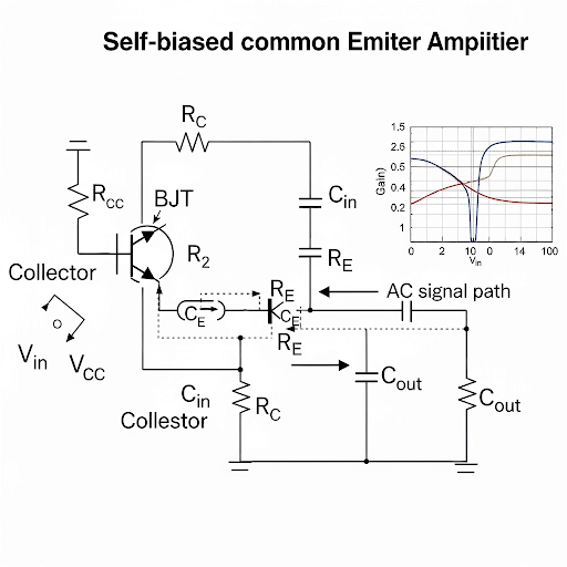
In this section, we explore the use of bypass capacitors in common emitter amplifiers, particularly with the self-bias configuration. Bypass capacitors help improve the frequency response of the amplifier by effectively bypassing the emitter resistor for AC signals. This allows the amplifier to achieve higher voltage gain by minimizing the feedback from the emitter to the base.
The section includes a revisitation of the previous discussion on frequency response and covers the derived expressions for voltage gain, input resistance, and output resistance of the self-biased common emitter amplifier. We analyze the components involved in the circuit and how the selected values of capacitive components influence the cutoff frequencies. Illustrative numerical examples are provided to reinforce the design guidelines, emphasizing how to choose appropriate capacitor values for both coupling and bypass applications.
Youtube Videos

Audio Book
Dive deep into the subject with an immersive audiobook experience.
Introduction to Bypass Capacitor
Chapter 1 of 4
🔒 Unlock Audio Chapter
Sign up and enroll to access the full audio experience
Chapter Content
So, what we said here it is this should be R and in addition to that R = R. So, this information these three expressions basically the information about the core CE amplifier, we are going to use to get the frequency response of this entire circuit.
Detailed Explanation
This chunk introduces the concept of bypass capacitors in the context of common emitter amplifiers. The use of the bypass capacitor impacts the frequency response of the amplifier by effectively reducing the resistance seen by the signal, thus influencing the gain across a range of frequencies. The relationship between resistances and the bypass capacitor leads to a more optimized response in the amplifier's performance.
Examples & Analogies
Imagine the bypass capacitor as a path in a crowded street (the resistance) that allows a shortcut to pedestrians (the signal), letting them reach their destination (the output) faster without hindrance from the crowd.
Impact on Frequency Response
Chapter 2 of 4
🔒 Unlock Audio Chapter
Sign up and enroll to access the full audio experience
Chapter Content
If we are arbitrarily selecting this C_E, then we may not get this frequency response. So, what you can do? Now, let me look into the frequency response of this CE amplifier having R_E and C_E together.
Detailed Explanation
In this part, the text discusses how the choice of the bypass capacitor affects the amplifier's frequency response. Choosing the right value for C_E is critical; if it is too high or too low, it might not adequately bypass the emitter resistor R_E, leading to suboptimal amplifier performance. Therefore, careful selection is necessary to achieve the desired frequency response.
Examples & Analogies
Think of C_E as the correct size of a filter for a water fountain. If the filter is too big, it may slow down the water flow; if it's too small, it won't filter properly. In both cases, choosing the right size ensures optimal performance, just like selecting the correct bypass capacitor ensures your amplifier responds well across the intended frequency range.
Effect of Gain with Bypass Capacitor
Chapter 3 of 4
🔒 Unlock Audio Chapter
Sign up and enroll to access the full audio experience
Chapter Content
So, to summarize, the voltage gain of the circuit can greatly increase with the presence of the bypass capacitor, which effectively shields the output gain from the drop usually contributed by R_E.
Detailed Explanation
This chunk highlights how the presence of the bypass capacitor can lead to higher voltage gain in the amplifier. The capacitor provides a low impedance path for AC signals, effectively short-circuiting the emitter resistor at mid-frequency, which allows the amplifier to operate with a higher gain than it would without the bypass capacitor.
Examples & Analogies
Consider a car engine’s performance. If a certain component (like an exhaust system) is too restrictive, the performance drops. A bypass capacitor acts like an optimized exhaust system that allows the engine (our amplifier) to run smoothly and efficiently, enhancing its overall power (voltage gain).
Conclusion and Design Considerations
Chapter 4 of 4
🔒 Unlock Audio Chapter
Sign up and enroll to access the full audio experience
Chapter Content
Depending on the value of the C_E, the effective resistance at this node will have a direct influence on the frequency response.
Detailed Explanation
This chunk concludes the discussion by emphasizing that the value of the bypass capacitor (C_E) not only directly influences the frequency response but also impacts the effective resistance in the circuit. This means engineers must carefully consider both the capacitance value and its effects on the overall circuit performance when designing the amplifier.
Examples & Analogies
When setting up a wifi network, choosing a router with a range that doesn’t cover your home is a mistake; it will lead to dead spots. The right choice of a bypass capacitor ensures that the amplifier 'covers' all necessary frequencies without dropouts, similar to how a well-placed router ensures good coverage throughout a space.
Key Concepts
-
Bypass Capacitor: A component that enhances the voltage gain by providing AC grounding for the emitter.
-
Frequency Response: Describes how the gain of an amplifier varies with frequency, including cutoff frequencies.
-
Voltage Gain: The measure of amplification provided by the amplifier, determined by the values of components in the circuit.
Examples & Applications
In a common emitter amplifier, a bypass capacitor with value 10µF may yield higher gain at low frequencies compared to using a larger value.
Selecting a coupling capacitor based on the operating frequency ensures minimal signal loss and improved frequency response.
Memory Aids
Interactive tools to help you remember key concepts
Rhymes
Bypass the resistor, gain is the goal; AC flows freely, keep it whole.
Stories
Imagine a river flowing around a rock; the bypass capacitor is like a bridge that lets water flow freely, increasing the river's speed—just like how it enhances gain.
Memory Tools
CAPTURES - Capacitors Allow Performance Tuning, Utilizing Reactance to Enhance Signal.
Acronyms
B.G.A.S. - Bypass for Gain and Amplified Signal, stressing the purpose of the bypass capacitor.
Flash Cards
Glossary
- Bypass Capacitor
A capacitor used in amplifier circuits that allows AC signals to pass while blocking DC signals, improving voltage gain.
- Cutoff Frequency
The frequency at which the gain of the amplifier begins to drop significantly, determining the bandwidth of the amplifier.
- Common Emitter Amplifier
A configuration of a bipolar junction transistor (BJT) amplifier where the emitter terminal is common to both input and output.
- Gain
The ratio of output voltage to input voltage in an amplifier; often expressed in decibels (dB).
Reference links
Supplementary resources to enhance your learning experience.