
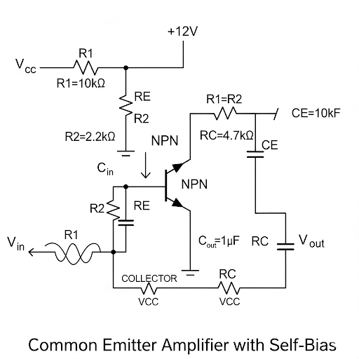
Common Emitter Amplifier with Self-Bias
Enroll to start learning
You’ve not yet enrolled in this course. Please enroll for free to listen to audio lessons, classroom podcasts and take practice test.
Interactive Audio Lesson
Listen to a student-teacher conversation explaining the topic in a relatable way.
Recap of Fixed Bias and Introduction to Self-Bias Amplifier
🔒 Unlock Audio Lesson
Sign up and enroll to listen to this audio lesson

Welcome back! Last time we discussed the common emitter amplifier with fixed bias. Today, we're diving into the self-bias configuration. Can anyone tell me why self-bias is beneficial?

Is it because it stabilizes the operating point?
Exactly! The self-bias provides stability against temperature variations and transistor replacement. Remember the abbreviation 'STAB' for Stability, Temperature, Amplification, and Biasing. Now, let's sketch the circuit diagram for a self-biased CE amplifier.

Does it involve additional resistors at the base?
Right! You have the resistors R1 and R2 creating a voltage divider. This is crucial for defining our base voltage, Vb. What do we know about the voltage at emitter, Ve?

It’s related to the base voltage by the drop across the emitter resistor.
Exactly, that drop is essential for proper operation. To summarize, the self-biased amplifier improves stability, which is vital for consistent output.
Analyzing the Small Signal Equivalent Circuit
🔒 Unlock Audio Lesson
Sign up and enroll to listen to this audio lesson

Let's analyze the small signal equivalent circuit. We need to find the voltage gain. Who remembers the formula?

Is it Av = -gm * Rd?
Close! The voltage gain formula considers the influence of the emitter resistor as well. Can anyone elaborate on this?
The gain also has to factor in the emitter resistor, right? So it's modified as -gm * Rd / (1 + gm * Re).
Exactly! That Re adds stability to our amplifier. Also, remember, gm is transconductance, which is dependent on the bias current. Let's run through a numerical example to illustrate this.
Can we also calculate input resistance?
Yes! The input resistance will be looking into the base, which combines Re and internal transistor resistance. So let's derive that.
Calculating the Frequency Response
🔒 Unlock Audio Lesson
Sign up and enroll to listen to this audio lesson
Next, let's talk about the frequency response. We have a high-pass characteristic from the coupling capacitor. What determines the cutoff frequency?
It's the RC product, right? Like C1 and R1?
Correct! The cutoff frequency f_c can be calculated as f_c = 1/(2πR1C1). Now, what’s the significance of upper cutoff frequency?
It defines the range where the amplifier loses gain due to C2?
Well said! Monitoring these cutoffs is crucial for design purposes. We also use bypass capacitors to improve our gain in mid frequency—any questions on this?
What if the bypass capacitor is too large?
Great question! A too-large capacitor could lower the frequency response excessively. Balance is key! Let’s summarize what we discussed today.
Introduction & Overview
Read summaries of the section's main ideas at different levels of detail.
Quick Overview
Standard
In this section, we delve into the common emitter amplifier with self-bias, analyzing its circuit elements and demonstrating how it operates through various examples. Key insights into calculating gain, input resistance, and output resistance are provided, reinforcing foundational knowledge essential for understanding this amplifier configuration.
Detailed
Common Emitter Amplifier with Self-Bias
The common emitter (CE) amplifier with self-bias configuration leverages feedback to stabilize the operating point of the transistor, enhancing the amplifier's performance. This section discusses the self-bias arrangement which involves an emitter resistor and two resistors connected to the base for generating a DC voltage. The analysis begins with a recap of the fixed bias CE amplifier before transitioning to the self-bias configuration, emphasizing the importance of circuit analysis and frequency response in application.
Circuit Elements
The CE amplifier consists of coupling capacitors, an emitter resistor, and importantly, base resistors which work together to achieve self-biasing. The effective circuit is modeled for small signal analysis which leads to understanding parameters like gain, input resistance, and output resistance.
Frequency Response
Several terms are introduced for cutoff frequencies, helping us model the overall frequency response as high-pass and low-pass characteristics. The discussion also covers the Laplace domain to explore the continuous frequency response, and specific methods to bypass unwanted gain impedance, further optimizing performance with bypass capacitors.
In conclusion, through numerical examples and a detailed breakdown of the small signal equivalent circuit, we glean how to calculate and optimize the design parameters crucial for real-world applications.
Youtube Videos

Audio Book
Dive deep into the subject with an immersive audiobook experience.
Introduction to Self-Biased Common Emitter Amplifier
Chapter 1 of 6
🔒 Unlock Audio Chapter
Sign up and enroll to access the full audio experience
Chapter Content
So, in the previous week we have discussed about common emitter amplifier with fixed bias and today we are going to discuss more about the self-biased common emitter amplifier.
Detailed Explanation
This chunk introduces the topic of self-biased common emitter amplifiers. Last week, students learned about common emitter amplifiers that used a fixed bias. Today's lesson will explore an alternative configuration— the self-biased amplifier— which automatically adjusts its operating point without needing fixed resistors or voltages for bias.
Examples & Analogies
Think of a self-biased amplifier like a thermostat in a home. Just as a thermostat adjusts the heating system based on the current temperature, a self-biased amplifier adjusts its own bias according to the needs of the circuit, responding automatically to changes.
Frequency Response Overview
Chapter 2 of 6
🔒 Unlock Audio Chapter
Sign up and enroll to access the full audio experience
Chapter Content
we will be going to discuss about the frequency response of common emitter amplifier with self-bias arrangement.
Detailed Explanation
This section focuses on the frequency response of the self-biased common emitter amplifier. Frequency response describes how the amplifier reacts to different input frequencies. Understanding this response is essential as it allows the design to maintain performance across a range of signals, which is particularly important in audio and communications applications.
Examples & Analogies
Imagine tuning a radio. You’ll notice that it sounds clearer at certain frequencies and distorted at others. In the same way, an amplifier needs to respond correctly to a range of frequencies to ensure clear sound output.
Circuit Analysis for Self-Biased CE Amplifier
Chapter 3 of 6
🔒 Unlock Audio Chapter
Sign up and enroll to access the full audio experience
Chapter Content
this is the small signal equivalent circuit coming from the CE part.
Detailed Explanation
In this segment, students will look at the small signal equivalent circuit of the common emitter configuration. This model simplifies the analysis of the amplifier's behavior by allowing us to focus on small variations around an operating point rather than the larger signals and broader behaviors.
Examples & Analogies
Similarly, architects often create scale models of buildings to study their designs in relation to their environment. In electronics, the small signal model helps us understand how the larger system operates under normal conditions without the complexity of larger signals.
Voltage Gain Calculation
Chapter 4 of 6
🔒 Unlock Audio Chapter
Sign up and enroll to access the full audio experience
Chapter Content
If we take the ratio of the two then that gives us the voltage gain A.
Detailed Explanation
This part details the calculation of voltage gain in the self-biased common emitter amplifier. Voltage gain is defined as the output signal voltage divided by the input signal voltage. By analyzing the circuit and identifying the resistances and active components involved, students can derive the formula for voltage gain.
Examples & Analogies
Consider it like a speaker. If the input sound (the voice you speak) is weak, but it comes out of the speaker much louder, the speaker has a high voltage gain. In amplifiers, achieving a proper gain ensures the signals are appropriately strengthened for further use.
Input Resistance Analysis
Chapter 5 of 6
🔒 Unlock Audio Chapter
Sign up and enroll to access the full audio experience
Chapter Content
input resistance we do have R ⫽ R and that dominates over this resistance.
Detailed Explanation
This section discusses input resistance in the self-biased common emitter amplifier. Input resistance affects how the amplifier interacts with preceding stages in a circuit. More resistance may imply less current drawn from the previous stage, affecting the overall circuit performance.
Examples & Analogies
Think about trying to fit a large volume of water through a narrow pipe. If the pipe is too narrow (high resistance), the flow (current) is reduced. In electronics, matching input resistance ensures the right amount of signal is fed into the amplifier.
Overall Frequency Response and System Behavior
Chapter 6 of 6
🔒 Unlock Audio Chapter
Sign up and enroll to access the full audio experience
Chapter Content
So, to get the frequency response of this CE amplifier with the emitter degenerator, what we can do here it is if you consider the first part this part...
Detailed Explanation
In this final chunk, the discussion culminates in understanding the overall frequency response of the amplifier. This involves assessing how the previously discussed characteristics—gain, input/output resistance, and circuit arrangement influence the final performance across different frequencies.
Examples & Analogies
It’s much like adjusting the equalizer on a stereo system to balance sound across various frequencies. Adjustments in each part of the system change how the overall sound (or frequency response) is perceived.
Key Concepts
-
Self-Bias: A method of biasing a transistor that uses feedback from the emitter to stabilize its operating point.
-
Voltage Gain: The factor by which an amplifier increases the amplitude of a signal.
-
Frequency Response: The output characteristics of the amplifier as a function of input frequency.
Examples & Applications
Example of calculating the voltage gain for a standard common emitter configuration.
Example of determining the input resistance in a common emitter amplifier setup.
Memory Aids
Interactive tools to help you remember key concepts
Rhymes
In Emitter bounces gain, resistors play the stabilizing game.
Stories
Imagine a self-tuning guitar. The strings adjust to maintain the perfect pitch, just as the self-bias preserves the ideal operating point in an amplifier.
Memory Tools
Remember 'CRAB' for Coupling, Resistors, Amplification, and Bypass.
Acronyms
SLIDE - Stability, Load, Input resistance, Decoupling, and Emitter gains.
Flash Cards
Glossary
- Common Emitter Amplifier
A basic amplifier configuration in which the output voltage is taken from the collector with respect to the emitter as a common reference.
- SelfBias
A configuration that uses feedback from the emitter to stabilize the operating point of a transistor amplifier.
- Transconductance (gm)
A measure of the capability of a device to convert input voltage to output current.
- Voltage Divider
A circuit configuration using two resistors to create a specific voltage level from a higher voltage source.
- Frequency Response
The output spectrum of an amplifier in response to a range of input frequencies.
Reference links
Supplementary resources to enhance your learning experience.