
Frequency Response Discussion
Enroll to start learning
You’ve not yet enrolled in this course. Please enroll for free to listen to audio lessons, classroom podcasts and take practice test.
Interactive Audio Lesson
Listen to a student-teacher conversation explaining the topic in a relatable way.
Introduction to Common Emitter Amplifier
🔒 Unlock Audio Lesson
Sign up and enroll to listen to this audio lesson

Today, we begin with the common emitter amplifier. Can anyone explain what a common emitter amplifier is?

Is it a type of amplifier where the emitter terminal is common to both the input and output?
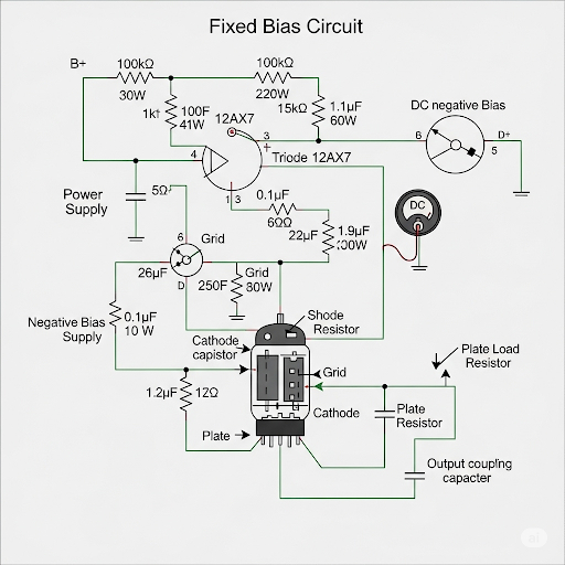
Exactly! And today, we'll explore both fixed bias and self-bias arrangements. Why do you think self-bias might be preferred?

Maybe because it enhances stability against variations in temperature and transistor properties?
Spot on! The self-bias arrangement helps maintain consistent operation under varying conditions.

How does it actually work in the circuit, though?
That's what we will uncover next. Let’s look at the circuit diagram representing a self-biased CE amplifier.
Remember, a useful way to remember the bias types is 'Fixed isn't flexible, but Self is stable'.
In summary, we've distinguished common emitter amplifiers and introduced self-biasing's benefits.
Frequency Response Analysis
🔒 Unlock Audio Lesson
Sign up and enroll to listen to this audio lesson

Moving on to frequency response—can anyone tell me why it’s important for amplifiers?
It determines how the amplifier behaves at different frequencies, right?
Exactly! For CE amplifiers, we look at three parts: the input CR circuit, the amplifier itself, and the output RC circuit.
What does each part contribute to the frequency response?
Good question! The CR circuit generally allows low-frequency signals to pass while filtering out high frequencies. Contrarily, the RC circuit does the opposite.
So, when we combine these responses, we get a complete picture of the amplifier's frequency response?
Precisely! Each part contributes a different aspect, leading to our overall response curve.
To help memorize: 'CR cuts high, RC lets low fly'.
So far, we’ve examined the roles of different sections in the frequency response.
Practical Applications and Design Considerations
🔒 Unlock Audio Lesson
Sign up and enroll to listen to this audio lesson
Now, let's apply what we've learned to numerical examples. Can anyone suggest a step in selecting capacitor values?

We need to determine the cutoff frequencies first?
Correct! Knowing the lower and upper cutoff frequencies helps us select appropriate capacitor values.
How do we calculate those cutoff frequencies?
Cutoff frequencies involve the resistive and capacitive components in the circuit. If we apply the basic formula, we can derive them systematically.
Can you give us a numerical example?
Certainly! If we have R = 1kΩ and C = 10μF, we can calculate the cutoff frequency using the formula f_c = 1/(2πRC).
Let’s summarize: Understanding cutoff frequencies allows for effective capacitor selection in CE amplifiers.
Introduction & Overview
Read summaries of the section's main ideas at different levels of detail.
Quick Overview
Standard
The frequency response of a common emitter amplifier emphasizes the differences between fixed bias and self-bias arrangements. The discussion involves understanding the key circuit components, their configurations, and numerical examples to illustrate the significance of capacitive and resistive elements in determining cutoff frequencies and overall circuit behavior.
Detailed
Frequency Response Discussion
In this section, we focus on the frequency response of the common emitter (CE) amplifier configuration with an emphasis on self-bias arrangements. We aim to understand the overall frequency response, including the analysis of coupling capacitors, the input resistance of the amplifier, and how these components influence the amplifier's performance in terms of cutoff frequencies and gain.
Key Points Covered:
- Self-Biased CE Amplifier: Introduction to the self-biasing mechanism and its significance compared to the fixed bias system previously discussed.
- Circuit Analysis: Detailed analysis of the circuit components, including RC and CR circuits and their resulting effects on the overall frequency response.
- Numerical Examples: Demonstrations of selecting values for capacitors and design guidelines based on specified cutoff frequencies.
- Frequency Response: The section explains how the frequency response is developed across different circuit sections—the input, amplifier, and output sections—highlighting the poles and their implications for high-pass and low-pass behaviors.
- The Role of Capacitors: Discussion on how coupling capacitors affect the signal transmission and overall performance of the amplifier.
By the end of this section, students should have a clear understanding of how to compute and interpret the frequency response of a self-biased common emitter amplifier, as well as the practical applications in design.
Youtube Videos

Audio Book
Dive deep into the subject with an immersive audiobook experience.
Overview of Frequency Response in Amplifiers
Chapter 1 of 6
🔒 Unlock Audio Chapter
Sign up and enroll to access the full audio experience
Chapter Content
The overall plan; as I said that in the previous week we have discussed about the frequency response of CE amplifier for which we have detailed discussion about R-C and C-R circuit and then you know we have discussed about the common source amplifier particularly with circuit analysis. Numerical portion it was not covered, so today we are going to discuss numerical examples of common source amplifier.
Detailed Explanation
In this introduction, we are recapping what was discussed in the previous class regarding the frequency response of common emitter (CE) amplifiers and common source amplifiers. The CE amplifier has both R-C (Resistor-Capacitor) and C-R (Capacitor-Resistor) circuits, which affect its frequency response, hence the earlier detailed discussions. Today, we aim to explore the numerical aspects of these amplifiers, particularly focusing on how to analyze them mathematically.
Examples & Analogies
Think of an amplifier as a speaker system for your home. Just as the quality of sound you hear can be influenced by the type of speakers and how they are set up (including any additional equalizers or filters), the frequency response of an amplifier is influenced by the resistance and capacitance in the circuit. If set well, you'll achieve the best sound (or amplification) possible.
Recap of Circuit Analysis
Chapter 2 of 6
🔒 Unlock Audio Chapter
Sign up and enroll to access the full audio experience
Chapter Content
In the previous week what we have discussed? It is in case if we have say common in any amplifier which is having say preceded C-R circuit and then followed by the R-C circuit, then the corresponding model of the circuit, it is given here.
Detailed Explanation
This part serves as a brief recap of the last lecture. We revisited how amplifiers consist of interconnected C-R and R-C circuits, leading to the overall behavior of the amplifier. Understanding how these parts interact is key to analyzing an amplifier's frequency response.
Examples & Analogies
Imagine making a smoothie. The ingredients (like fruits and yogurt) need to be mixed together in the right proportions (similar to electrical components in a circuit) for the best taste (output response). If you do not add enough of one ingredient (e.g., resistance), the smoothie might be too thick and not smooth (the frequency response is not optimal).
Analysis of Self-Biased Common Emitter Amplifier
Chapter 3 of 6
🔒 Unlock Audio Chapter
Sign up and enroll to access the full audio experience
Chapter Content
Let us; so, that is what we have discussed in the previous day, now we are going to discuss about CE amplifier having self-biased arrangement.
Detailed Explanation
We are now shifting our focus to a specific type of CE amplifier — the self-biased arrangement. This configuration is important because it allows the amplifier to operate consistently over wider ranges of input signals and maintains bias without external voltage sources. This section will break down the mechanics of this setup.
Examples & Analogies
Think of a self-biased amplifier like a self-regulating garden. Instead of needing constant water (external bias) to maintain the plants, a self-sustaining garden uses rainwater and soil to keep plants thriving at optimal conditions, similar to how self-bias maintains the amplifier's operation.
Core Circuit Analysis for Common Emitter Amplifier
Chapter 4 of 6
🔒 Unlock Audio Chapter
Sign up and enroll to access the full audio experience
Chapter Content
Yes; so, this is the core part of the circuit and as I said that the signal we are directly feeding here at the input and the output we are observing at this point.
Detailed Explanation
This section analyzes the core of the self-biased CE amplifier. Here, the input signal affects the output directly, and we need to understand how these interactions create gain. The concepts of input and output voltage connections are critical at this stage, as these relationships define the amplifier's behavior.
Examples & Analogies
This is like someone telling you a joke (input) that makes everyone laugh (output). The strength of the joke (signal gain) depends directly on how well it is delivered. Similarly, the gain in an amplifier depends on the input voltage and the reactions of the components within.
Voltage Gain and Input Resistance
Chapter 5 of 6
🔒 Unlock Audio Chapter
Sign up and enroll to access the full audio experience
Chapter Content
So, to summarize, so what we are obtaining here it is this circuit, this circuit is having voltage gain of a and then input resistance it is R ⫽ R and then r + R (1 + β).
Detailed Explanation
In this segment, we explore how to calculate the voltage gain and input resistance of the self-biased CE amplifier. The voltage gain is a measure of how much the output signal increases compared to the input signal. We also express the input resistance in terms of the circuit components, highlighting the complexities introduced by the self-bias configuration.
Examples & Analogies
Imagine a speaker that can either amplify or muffle sound based on how closely you are standing to it. The closer you are (lower input resistance), the better you can hear (higher gain) the music. Similarly, in an amplifier, the right balance between input resistance and gain can significantly influence the output quality.
Overall Frequency Response
Chapter 6 of 6
🔒 Unlock Audio Chapter
Sign up and enroll to access the full audio experience
Chapter Content
So, what we said here it is this should be R and in addition to that R = R . So, this information, these three expressions basically the information about the core CE amplifier, we are going to use to get the frequency response of this entire circuit.
Detailed Explanation
Finally, we discuss how the gained information about the voltage gain and input resistance will enable us to derive the overall frequency response for the whole circuit. We will combine the frequency responses of the individual components (C-R and R-C sections) to understand how they work together in amplifying a signal and influencing bandwidth.
Examples & Analogies
Imagine piecing together a jigsaw puzzle. Each piece represents a part of the amplifier's circuit, and when they come together, they create a clear picture (overall frequency response). The better the pieces fit together, the clearer the final image will be, which is analogous to achieving optimal performance from the amplifier.
Key Concepts
-
Self-Bias Arrangement: A configuration that stabilizes the amplifier operation via feedback mechanisms.
-
RC and CR Circuits: These circuits influence the cutoff frequencies and overall frequency response characteristics.
-
Voltage Gain: Understanding how to calculate and interpret voltage gain is crucial for amplifier design.
Examples & Applications
If an amplifier has R = 1kΩ and C = 10μF, the cutoff frequency f_c = 1/(2πRC) would be approximately 15.9 Hz.
A self-biased common emitter amplifier generally provides a more stable gain under temperature variations than a fixed bias configuration.
Memory Aids
Interactive tools to help you remember key concepts
Rhymes
In the CE, the emitter's key, common to both, you see!
Stories
Once upon a circuit, a signal so bright traveled from input to output, shining with all its might. But each frequency had its tale, some passed, and others would fail, guides through RC circuits and capacitance would prevail.
Memory Tools
FIC - Frequency response, Input-output connection, Configuration type.
Acronyms
CAS - Common Emitter, Amplifier, Self-bias.
Flash Cards
Glossary
- Common Emitter Amplifier
An amplifier configuration where the emitter terminal is common to both the input and output, often used for voltage amplification.
- SelfBiased
A type of circuit biasing technique that relies on feedback from the emitter resistor to set the bias voltage.
- Frequency Response
The output spectrum of an amplifier obtained by varying the input frequency, illustrating how gain varies with frequency.
- Coupling Capacitor
A capacitor used to connect two circuits, allowing AC signals to pass while blocking DC components.
- Cutoff Frequency
The frequency at which the output power drops to half its peak value, marking the separation between passband and stopband.
- Voltage Gain
The ratio of output voltage to input voltage in an amplifier, typically expressed in decibels.
Reference links
Supplementary resources to enhance your learning experience.