
THE PARALLEL PLATE CAPACITOR
Enroll to start learning
You’ve not yet enrolled in this course. Please enroll for free to listen to audio lessons, classroom podcasts and take practice test.
Interactive Audio Lesson
Listen to a student-teacher conversation explaining the topic in a relatable way.
Understanding Parallel Plate Capacitors
🔒 Unlock Audio Lesson
Sign up and enroll to listen to this audio lesson

Good morning, everyone! Today we're going to dive into the world of parallel plate capacitors. Can anyone tell me what they understand by a capacitor?

Isn't it a device used to store electrical energy?
Exactly! A capacitor stores energy in an electric field. Now, a parallel plate capacitor consists of two conducting plates separated by an insulating material—what we call a dielectric. Can anyone guess what happens when we connect this capacitor to a battery?

The plates get charged?
That's right! The positive plate accumulates positive charge, and the negative plate accumulates a negative charge. This generates an electric field between the plates. Remember: **Q = CV** represents the relationship between charge, capacitance, and voltage. Q is directly proportional to V.

So more charge means higher voltage?
Exactly! Voltage increases with an increase in charge. Let’s use the acronym **CAP** to remember: Charge, Area, Potential. Charge is directly related to the area of the plates and the potential difference. Are we all clear on that?
Yes!
Great! To summarize, parallel plate capacitors can hold charges proportional to their capacitance and the voltage supplied.
Calculating Capacitance
🔒 Unlock Audio Lesson
Sign up and enroll to listen to this audio lesson

Now, let’s look deeper into how we calculate capacitance. The formula is given by $$C = \frac{\varepsilon_0 A}{d}$$. Who can tell me what each variable represents?

C is capacitance, \(A\) is the area of the plates, and \(d\) is the distance between them.
Exactly! And \(\varepsilon_0\) is the vacuum permittivity. So, if we increase the area of the plates, what happens to capacitance?
It increases!
Correct! Capacitance increases with a larger area. Conversely, if the distance **d** increases, what happens to capacitance?
It decreases.
That’s right! Remember the mnemonic: **FAR** for 'farther decreases; closer increases'. What else affects capacitance?
The dielectric material between the plates!
Exactly! The presence of a dielectric increases capacitance by a factor known as the dielectric constant **K**. So the modified capacitance becomes: $$C = K C_0$$ where \( C_0 \) is the capacitance in a vacuum. Is everyone following along?
Yes!
Wonderful! In summary, the key factors influencing the capacitance of parallel plate capacitors are the area, distance, and the properties of the dielectric used.
Applications of Parallel Plate Capacitors
🔒 Unlock Audio Lesson
Sign up and enroll to listen to this audio lesson
Finally, let’s explore where you might encounter parallel plate capacitors in the real world. Can anyone share some examples?
They are often found in electronic devices?
Absolutely! They're used in tuning circuits, filters in radios, and more. They are also critical in energy storage applications, such as in defibrillators. Now, how about we reflect on the safety aspects of these devices?
They can hold a lot of charge, which can be dangerous!
Correct! High-voltage capacitors can pose shock hazards. Always ensure capacitors are discharged before handling. Keep in mind the acronym **DASH**—Discharge Always Safe Handling. Any confusion on this topic?
No, it's clear!
Great! In summary, we’ve discussed various applications of parallel plate capacitors and the safety measures to take when dealing with them.
Introduction & Overview
Read summaries of the section's main ideas at different levels of detail.
Quick Overview
Standard
The section provides an in-depth look at parallel plate capacitors, detailing how they consist of two large parallel conducting plates separated by a distance. It explores how the electric field is established between the plates and how the capacitance can be calculated based on the plate area and distance between them. Additionally, the impact of dielectrics on capacitance is addressed, along with relevant applications.
Detailed
Detailed Summary
A parallel plate capacitor comprises two large parallel conductors that store electrical energy by maintaining a potential difference between them. The plates are separated by a distance d, and an insulating material may be placed between them, influencing their capacitance.
Key Concepts Covered:
- Electric Field Calculation: The electric field E between the plates can be derived from surface charge density and establishes that the field is uniform due to the large area of the plates relative to their separation.
- Capacitance Formula: The capacitance C of the capacitor is defined as:
$$C = \frac{Q}{V} = \frac{\varepsilon_0 A}{d}$$
where Q is the charge stored, V is the potential difference, A is the area of the plates, and d is their separation. The permittivity \( \varepsilon_0 \) defines the electric field strength in a vacuum. - Effect of Dielectrics: Introducing a dielectric increases the capacitance by a factor known as the dielectric constant K, modifying the effective capacitance of the capacitor used in various applications.
Significance:
Understanding parallel plate capacitors is crucial as they are widely used in electronic circuits, energy storage, and signal processing.
Youtube Videos


Audio Book
Dive deep into the subject with an immersive audiobook experience.
Introduction to Parallel Plate Capacitors
Chapter 1 of 5
🔒 Unlock Audio Chapter
Sign up and enroll to access the full audio experience
Chapter Content
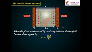
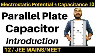
A parallel plate capacitor consists of two large plane parallel conducting plates separated by a small distance. We first take the intervening medium between the plates to be vacuum. The effect of a dielectric medium between the plates is discussed in the next section.
Detailed Explanation
A parallel plate capacitor is a device used to store electric charge. It is comprised of two flat plates that are positioned parallel to each other. When these plates are charged with equal but opposite charges, an electric field is created between them, which allows the capacitor to store electrical energy. The space between the plates can be filled with air (vacuum) initially, and later this space can be filled with a dielectric material to enhance its capacitance.
Examples & Analogies
Think of a parallel plate capacitor like a water tank with two flat roofs (the plates) and a space between them. When you fill the tank with water (charge), you manage to store it between the two roofs. The water pressure between the roofs represents the stored energy.
Electric Field Between Plates
Chapter 2 of 5
🔒 Unlock Audio Chapter
Sign up and enroll to access the full audio experience
Chapter Content
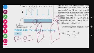
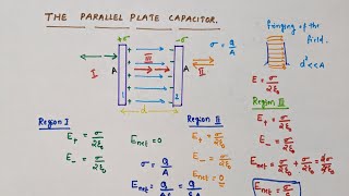
The two plates have charges Q and –Q. Since d is much smaller than the linear dimension of the plates (d² << A), we can use the result on electric field by an infinite plane sheet of uniform surface charge density.
Detailed Explanation
In a parallel plate capacitor, the positively charged plate creates a uniform electric field directed away from it, while the negatively charged plate creates an electric field directed towards it. Because the distance between the plates is much smaller than their area, the electric fields produced by the plates can be treated as uniform across the space between them. This uniformity implies that the total electric field (E) between the plates can be determined using the formula relating charge density to the electric field.
Examples & Analogies
Imagine holding two flat balloons, one inflated positively and the other negatively. The electric fields they generate push or pull on each other in a uniform manner across the space around them, similar to how electric fields work in parallel plate capacitors.
Capacitance Formula
Chapter 3 of 5
🔒 Unlock Audio Chapter
Sign up and enroll to access the full audio experience
Chapter Content
The capacitance C of the parallel plate capacitor is then given by C = ε₀(A/d), where A is the area of each plate and d is the separation between them.
Detailed Explanation
The capacitance (C) of a parallel plate capacitor is a measure of its ability to store electric charge per unit voltage. The formula indicates that capacitance increases with the area of the plates (A) and decreases with the increase in the distance (d) between the plates. Therefore, larger plates or smaller separations will result in a higher capacitance, allowing the capacitor to store more charge at the same voltage.
Examples & Analogies
Consider this like a larger tank that can hold more water (charge) if it has a bigger surface area and less distance (height) between its base and roof. If the tank were taller (greater d), it wouldn't be able to hold as much water for the same tank diameter.
Effect of Dielectric on Capacitance
Chapter 4 of 5
🔒 Unlock Audio Chapter
Sign up and enroll to access the full audio experience
Chapter Content
With the understanding of the behaviour of dielectrics in an external field developed in Section 2.10, let us see how the capacitance of a parallel plate capacitor is modified when a dielectric is present.
Detailed Explanation
When a dielectric material is inserted between the plates of a parallel plate capacitor, the capacitance increases. The dielectric becomes polarized in the electric field, which reduces the overall electric field between the plates, allowing more charge to be stored for the same voltage. The capacitance with a dielectric is given by the relationship C = K * C₀, where K is the dielectric constant and C₀ is the capacitance in a vacuum.
Examples & Analogies
Think of a sponge filling up with water. When the sponge (dielectric) is added to your water tank (capacitor), it allows you to hold more water than without it. The more 'absorbent' the sponge (higher K), the more water (charge) you can hold.
Capacitors in Series and Parallel
Chapter 5 of 5
🔒 Unlock Audio Chapter
Sign up and enroll to access the full audio experience
Chapter Content
The general formula for effective capacitance of a series combination of n capacitors: 1/C = 1/C₁ + 1/C₂ + ... + 1/Cₙ. In the parallel combination: C = C₁ + C₂ + ... + Cₙ.
Detailed Explanation
When capacitors are arranged in series, the total capacitance decreases, as described by the inverse relationship in the formula. Conversely, when capacitors are connected in parallel, the capacitance simply adds up. This shows how different configurations affect the overall ability of the system to store charge.
Examples & Analogies
Imagine several water tanks connected. In series, the flow is limited by the smallest tank; hence the capacity drops. In parallel, each tank adds to the total capacity, like adding more tanks to hold more water at once.
Key Concepts
-
Electric Field Calculation: The electric field E between the plates can be derived from surface charge density and establishes that the field is uniform due to the large area of the plates relative to their separation.
-
Capacitance Formula: The capacitance C of the capacitor is defined as:
-
$$C = \frac{Q}{V} = \frac{\varepsilon_0 A}{d}$$
-
where Q is the charge stored, V is the potential difference, A is the area of the plates, and d is their separation. The permittivity \( \varepsilon_0 \) defines the electric field strength in a vacuum.
-
Effect of Dielectrics: Introducing a dielectric increases the capacitance by a factor known as the dielectric constant K, modifying the effective capacitance of the capacitor used in various applications.
-
Significance:
-
Understanding parallel plate capacitors is crucial as they are widely used in electronic circuits, energy storage, and signal processing.
Examples & Applications
When a parallel plate capacitor with an area of 1 m² and a separation of 1 mm fills the space between its plates with a dielectric of K=5, its capacitance increases significantly to accommodate larger stored charge without increasing the volume.
Memory Aids
Interactive tools to help you remember key concepts
Rhymes
Parallel plates and charged they stay, storing energy every single day.
Stories
Imagine two friends holding hands across a distance, creating a bridge of energy. The more they stretch, the more energy builds up between them.
Memory Tools
CAP—Charge, Area, Potential: Key components of capacitance.
Acronyms
DASH—Discharge Always Safe Handling
Safety rule for dealing with capacitors.
Flash Cards
Glossary
- Capacitance
A measure of a capacitor's ability to store charge, defined as the ratio of charge stored to the voltage across the capacitor.
- Dielectric
An insulating material placed between conductors in a capacitor that increases capacitance when introduced.
- Electric Field
A field around charged particles that exerts force on other charged objects.
- Permittivity
A measure of how an electric field interacts with a dielectric material.
Reference links
Supplementary resources to enhance your learning experience.