
Half Wave Rectifier
Enroll to start learning
You’ve not yet enrolled in this course. Please enroll for free to listen to audio lessons, classroom podcasts and take practice test.
Interactive Audio Lesson
Listen to a student-teacher conversation explaining the topic in a relatable way.
Introduction to Rectification
🔒 Unlock Audio Lesson
Sign up and enroll to listen to this audio lesson

Today, we will learn about Half Wave Rectifiers. Can anyone tell me what rectification means?

Isn't it about converting AC to DC?
Exactly! Rectification transforms alternating current, which reverses direction, into direct current, which flows in only one direction. Now, why do you think this is important?

Most electronic devices need DC to operate.
That's correct! And a Half Wave Rectifier uses a simple diode to achieve this. Can someone remind me what a diode does?

A diode allows current to flow in one direction only!
Well done! This characteristic is fundamental to how a Half Wave Rectifier works.
How Half Wave Rectifiers Function
🔒 Unlock Audio Lesson
Sign up and enroll to listen to this audio lesson

Let’s dive deeper into how a Half Wave Rectifier operates. What happens during the positive half-cycle of AC?

The diode becomes forward-biased and allows current to flow.
Correct! And during the negative half-cycle?
The diode is reverse-biased, so current does not flow.
Exactly! This leads to a pulsating DC output. Can anyone explain how this output looks on a graph?
It shows peaks during the positive cycles and flatlines during the negative cycles!
Well articulated! This output is also called pulsed DC.
Applications of Half Wave Rectifiers
🔒 Unlock Audio Lesson
Sign up and enroll to listen to this audio lesson
Now, let’s explore where we use Half Wave Rectifiers. Can anyone think of any applications?
I think they are used in power supplies!
Yes! They are commonly found in power supplies and battery chargers. What are some advantages or disadvantages of using them?
They are simple and cheap, but their efficiency is low.
That’s a fair point. They can waste energy and produce a lot of ripple in the output. Let's remember, this is why, in many cases, full wave rectifiers might be preferred!
Introduction & Overview
Read summaries of the section's main ideas at different levels of detail.
Quick Overview
Standard
The Half Wave Rectifier is a simple electronic circuit that utilizes one PN junction diode to convert alternating current (AC) into direct current (DC). This circuit only allows the positive half of the AC waveform to pass through, effectively blocking the negative half, which results in a pulsating DC output.
Detailed
Overview
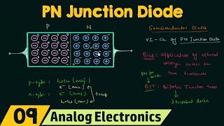
A Half Wave Rectifier is a fundamental application of the PN junction diode, primarily designed to convert alternating current (AC) to direct current (DC). By allowing current flow during only one half of the input AC cycle, the Half Wave Rectifier produces a pulsed output that is essential for various electronic applications.
Key Points:
- Single Diode Use: The rectifier employs a single diode to create a pathway for current flow.
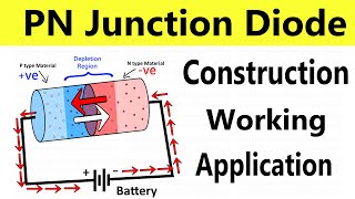
- Operation: During the positive half-cycle of AC, the diode is forward-biased, allowing current to pass. During the negative half-cycle, the diode becomes reverse-biased, thus blocking current.
- Output Characteristics: The output voltage is not smooth; it has gaps corresponding to the blocked negative cycles, resulting in a series of pulses.
- Applications: Commonly used in power supplies, battery chargers, and signal demodulation.
Youtube Videos


Audio Book
Dive deep into the subject with an immersive audiobook experience.
Overview of Half Wave Rectifier
Chapter 1 of 3
🔒 Unlock Audio Chapter
Sign up and enroll to access the full audio experience
Chapter Content
Half Wave Rectifier
● Uses one diode.
● Output only for one half of the AC cycle.
Detailed Explanation
A half wave rectifier is a circuit that converts alternating current (AC) into direct current (DC). The primary characteristic of a half wave rectifier is that it uses only one diode. This means that it allows current to pass through only during one half of the AC cycle - specifically, during the positive half of the waveform. In the negative half, the diode blocks current flow, resulting in the rectification of the input AC signal.
Examples & Analogies
Imagine water flowing through a pipe that has a valve. When the valve (the diode) is open, water can flow; when it’s closed, water cannot pass through. In this case, the half wave rectifier allows the flow of current (water) only during one part of the cycle, similar to how the valve controls the water flow. Thus, the output current is available only during one half of the AC voltage waveform.
Working Principle of Half Wave Rectifier
Chapter 2 of 3
🔒 Unlock Audio Chapter
Sign up and enroll to access the full audio experience
Chapter Content
● The diode conducts during the positive half cycle and blocks during the negative half cycle.
Detailed Explanation
During the operation of a half wave rectifier, when the input AC voltage is positive (above zero volts), the diode becomes forward-biased. This means that the diode allows current to flow through it, resulting in a positive output voltage. Conversely, when the AC voltage becomes negative (below zero volts), the diode becomes reverse-biased, and it does not conduct current. This process creates an output waveform that is zero for the negative half of the input wave, hence allowing only the positive half-cycle to pass through.
Examples & Analogies
Think of a one-way street where cars can only go in one direction. Cars (current) can move forward during the daytime (when the input AC voltage is positive), but at night (when the voltage is negative), the cars cannot move at all. This ‘one-way’ operation creates a current flow that only reflects the daytime activities, similar to how the half wave rectifier functions.
Advantages and Disadvantages
Chapter 3 of 3
🔒 Unlock Audio Chapter
Sign up and enroll to access the full audio experience
Chapter Content
Advantages: Simple design and low cost.
Disadvantages: Low efficiency and poor output quality.
Detailed Explanation
The half wave rectifier has notable advantages, including its simple design, which means easy implementation and low manufacturing costs. However, it also has significant disadvantages. One major drawback is its low efficiency because it utilizes only half of the input AC voltage for output. Additionally, the output waveform lacks smoothness, producing a ripple effect due to the absence of current during the negative half cycle. This poor output quality can make it unsuitable for certain applications requiring stable DC power.
Examples & Analogies
Consider a flashlight powered by batteries. A simple flashlight can turn on but may flicker if the batteries are low or of poor quality. Just like the half wave rectifier, it’s easy to use (simple design) but may not provide a steady beam of light (poor output quality) if the source isn’t consistent. More advanced flashlights (like full-wave rectifiers) provide a steadier light, similar to how other rectification methods improve efficiency and output quality.
Key Concepts
-
AC to DC Conversion: The process of changing alternating current into direct current.
-
Diode Functionality: A diode allows current to flow only in one direction.
-
Pulsating DC: The output of a Half Wave Rectifier that exhibits a series of peaks and voids.
Examples & Applications
The common wall charger for mobile devices that often uses a Half Wave Rectifier to convert AC from wall outlets into DC.
Signal demodulation in radios, where Half Wave Rectifiers are used to extract audio signals from the carrier wave.
Memory Aids
Interactive tools to help you remember key concepts
Rhymes
Half the wave, that's how we save, converting current, it's what we crave!
Stories
Imagine a brave little diode standing guard at a gate, letting only the friendly AC current pass through during the happy day and slamming shut when the less friendly current tries to come in.
Memory Tools
To remember how a Half Wave Rectifier works, think 'AC-PD'. 'AC' for Alternating Current, and 'PD' for Positive Direction only.
Acronyms
RDC - Rectification of Direct Current
Reflects how the Half Wave Rectifier operates.
Flash Cards
Glossary
- Half Wave Rectifier
A circuit that converts AC to DC using a single diode, allowing current flow only during one half of the AC cycle.
- Pulsating DC
An electrical output that varies in amplitude, typically resembling a series of peaks, characteristic of a Half Wave Rectifier.
- Forward Bias
A condition where the voltage applied to a diode allows current to flow through it.
- Reverse Bias
A condition where the voltage applied to a diode prevents current from flowing through it.
Reference links
Supplementary resources to enhance your learning experience.