
Example 4-1: Truss, Method of Joints
Enroll to start learning
You’ve not yet enrolled in this course. Please enroll for free to listen to audio lessons, classroom podcasts and take practice test.
Interactive Audio Lesson
Listen to a student-teacher conversation explaining the topic in a relatable way.
Introduction to Truss Analysis
🔒 Unlock Audio Lesson
Sign up and enroll to listen to this audio lesson

Today, we're diving into the analysis of trusses using the method of joints. Can anyone tell me what a truss is?

Isn't it a structure made of straight members, like triangles?

Yeah! They help support loads, right?
Exactly! Trusses are composed of triangular elements that are efficient in carrying loads. In analyzing trusses, we're concerned about internal forces. Let's remember: Tension is positive, and compression is negative. Can you recall this rule during our analysis?

Like, if we assume a member is in tension, and our calculation gives us a negative value, then it's actually in compression?
Correct! That’s a key aspect of the method. Now, let’s explore how we can analyze forces at a joint.
Understanding the Method of Joints
🔒 Unlock Audio Lesson
Sign up and enroll to listen to this audio lesson

When analyzing any joint in a truss, we start with equilibrium equations. At each joint, the sum of horizontal forces and the sum of vertical forces should be zero. Can anyone tell me why this is important?
To ensure that there’s no movement, right?
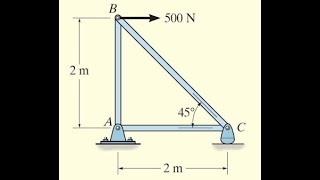
Exactly! No movement means the truss is stable. Let's apply this to a joint. For example, at node B, we have forces acting along the x and y axes. Who can help me write the equilibrium equations for node B?

We would set the sum of forces in the x-direction to zero and the sum of forces in the y-direction to zero.
Right! This method will allow us to determine the forces in the truss members connected at that joint. Remembering to include all acting forces is crucial!
Calculating Forces at Node B
🔒 Unlock Audio Lesson
Sign up and enroll to listen to this audio lesson
"Let’s calculate the forces at node B. Given that
Finalizing Results and Understanding Compression
🔒 Unlock Audio Lesson
Sign up and enroll to listen to this audio lesson
After calculations, we might find some members showing compressive forces. Remember, what does it mean if a force is negative?
That means the assumption we made about it being in tension was wrong!
Exactly! Understanding this helps engineers make better design choices. How can we relate our results to the design of trusses?
We can use this to choose materials that can handle compression efficiently, right?
Absolutely! Each decision impacts the overall safety and function of the structure. Great job everyone!
Introduction & Overview
Read summaries of the section's main ideas at different levels of detail.
Quick Overview
Standard
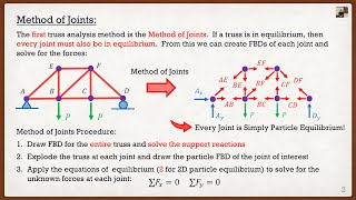
The method of joints is utilized to analyze a given truss by focusing on the equilibrium of forces at each joint. This section provides detailed calculations and results for specific nodes in a truss structure.
Detailed
Detailed Summary
The method of joints is an essential technique in structural engineering for determining the forces within truss members. In this example, we apply this method to analyze a truss system by examining individual joints in the truss and ensuring that the forces acting at each joint are in equilibrium. Each joint's sum of vertical and horizontal forces is set to zero, leading to equations that facilitate the calculation of tensile and compressive forces in the specific truss members. The forces are labeled as positive when tensile and negative when compressive. We analyze various nodes, substitute known values, and solve the equations step-by-step to find the internal forces within the members. Such analysis is critical for ensuring the structural integrity and performance of trusses in civil engineering applications.
Youtube Videos


Audio Book
Dive deep into the subject with an immersive audiobook experience.
Analyzing Node B
Chapter 1 of 4
🔒 Unlock Audio Chapter
Sign up and enroll to access the full audio experience
Chapter Content
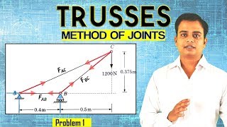
Node B:
(+-)(cid:6)F = 0; F = 43:5 k Tension
x BC
)(+ 6)(cid:6)F
y = 0; F
BH
= 20 k Tension
)
Detailed Explanation
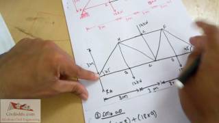
In this part of the analysis, we start by looking at Node B of the truss. We apply the equations of equilibrium to this joint. The first part, where it says (cid:6)F = 0, indicates that the sum of all forces acting on Node B in the x-direction must equal zero. Here, we find that the force in member BC is 43.5 kN in tension. The second equation states that the sum of forces in the y-direction is also zero, resulting in a force of 20 kN in tension for member BH. This means that both of these members are pulling away from Node B, which is characteristic of tension forces.
Examples & Analogies
Imagine you are holding two ropes at an angle - one in your left hand and one in your right hand. If you pull on both ropes, you are exerting tension on them. In the truss, Node B works in a similar way, with members BC and BH pulling in opposite directions to maintain balance.
Analyzing Node H
Chapter 2 of 4
🔒 Unlock Audio Chapter
Sign up and enroll to access the full audio experience
Chapter Content
Node H:
(+-)(cid:6)F = 0; F F F = 0
x
)(AHx
(cid:0)HCx
(cid:0)HGx
43:5 24 (F ) 24 (F ) = 0
(cid:0) p242+322 HC (cid:0) p242+102 HG
(+ 6)(cid:6)F
y = 0;
)
F
AHy
+F
HCy
(cid:0)12 (cid:0)F
HGy
(cid:0)20 = 0
58+ 32 (F ) 12 10 (F ) 20 = 0
Detailed Explanation
Next, we analyze Node H, where we again write the equations of equilibrium. For the x-direction, the forces along members AH, HC, and HG must balance out to zero. This gives us an equation based on the tensions in these members. Similarly, for the y-direction, the forces must sum to zero as well. Solving these two equations helps us find the forces in members HC and HG, determining one is in tension and the other in compression.
Examples & Analogies
Think of balancing a seesaw. If one side of the seesaw goes up, the other side must go down, or else it will tip over. In Node H, the forces acting on it must also balance out just like the seesaw, ensuring stability in the structure.
Calculating Forces
Chapter 3 of 4
🔒 Unlock Audio Chapter
Sign up and enroll to access the full audio experience
Chapter Content
This can be most conveniently written as
0:6 0:921 F 7:5
HC = (cid:0) (4.2)
0:8 0:385 F 52
" #( HG ) ( )
(cid:0)
Detailed Explanation
After setting up the equations based on our equilibrium analysis, we reach the stage where we can solve for the unknown forces in the truss members. Here, we denote HC and HG as the forces in respective members and organize our equations for easier calculation. By substituting values, we can solve for FHC and FHG.
Examples & Analogies
Imagine solving a puzzle where each piece fits perfectly with others that surround it. Similarly, in detailed calculations, each force relates to others, fitting together to reveal a complete picture of internal forces acting within the truss.
Finalizing the Analysis
Chapter 4 of 4
🔒 Unlock Audio Chapter
Sign up and enroll to access the full audio experience
Chapter Content
Solving we obtain
F = 7:5 k Tension
HC
(cid:0)
F = 52 k Compression
HG
Detailed Explanation
Upon solving our equations, we find the force in member HC is 7.5 kN in tension, while the force in member HG is 52 kN in compression. This information is crucial for understanding how the truss distributes loads and how it will behave under certain conditions.
Examples & Analogies
When you analyze the stress on a bridge, you might discover which cables are securing the bridge (tension) and which are supporting it (compression). Similarly, in our truss analysis, knowing which members are under tension and which are compressed helps engineers ensure the structure is safe and reliable.
Key Concepts
-
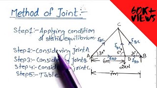
Method of Joints: A technique used for determining member forces in truss structures. Each joint's equilibrium must be assessed.
-
Equilibrium: Ensuring that the sum of all forces at a joint equals zero, indicating no resultant movement.
Examples & Applications
In analyzing Node B of a truss, horizontal forces are set to zero: F_BC + F_BH = 0, and vertical forces: F_AH + F_BH = total vertical load applied.
If solving yields a negative force for a member assumed to be in tension, it indicates that the member is actually in compression.
Memory Aids
Interactive tools to help you remember key concepts
Rhymes
Trusses hold tight in shapes of three, balance the forces, just like a tree.
Stories
Imagine a bridge made of triangles. One day, it gets a load from a truck, and the struts hold firm. If one strut pulls back, you know it's in tension, while if one bulges inward, it’s under compression.
Memory Tools
Forces at each joint, remember ABC - A=Assume Tension, B=Balance Forces, C=Check Results.
Acronyms
J.O.I.N.T
Just One Important Node to think about when analyzing trusses.
Flash Cards
Glossary
- Truss
A structure made of members arranged in a triangular framework to support loads.
- Method of Joints
A technique to analyze trusses by evaluating forces acting on each joint.
- Equilibrium
A condition where the sum of forces acting on a body is zero, resulting in no movement.
- Tension
A force that stretches a member, pulling it away from its joint.
- Compression
A force that compresses a member, pushing it towards its joint.
- Node
A joint where two or more members meet in a truss.
- Force
An interaction that, when unopposed, will change the motion of an object.
Reference links
Supplementary resources to enhance your learning experience.