
TRUSSES
Enroll to start learning
You’ve not yet enrolled in this course. Please enroll for free to listen to audio lessons, classroom podcasts and take practice test.
Interactive Audio Lesson
Listen to a student-teacher conversation explaining the topic in a relatable way.
Introduction to Trusses
🔒 Unlock Audio Lesson
Sign up and enroll to listen to this audio lesson

Welcome class! Today we'll be exploring trusses, an essential component in structural engineering. Can anyone tell me what a truss is?

Isn't it a structure made of several triangular components that can handle forces?
Exactly, Student_1! Trusses are made from one-dimensional components, transferring only axial forces. They can handle both tensile and compressive forces. Remember, trusses are much different from cables, which can only carry tensile forces.

What are the main assumptions we make when analyzing trusses?
Good question! We assume that bars are pin-connected, that joints act like frictionless hinges, and that loads are applied solely at the joints. This simplification helps in analyzing and designing trusses effectively.
To remember these assumptions, we can use the acronym **'PCI'**: Pin-connected, Frictionless, and at the Intersection of loads. Can anyone summarize what we just covered?

Trusses are made of triangular components, and we assume they're pin-connected and that loads apply only at joints!
Determinacy and Stability
🔒 Unlock Audio Lesson
Sign up and enroll to listen to this audio lesson

Next, let’s discuss determinacy and stability in trusses. Who can define what it means for a truss to be statically determinate?

I think it means that you can calculate all the bar forces using the equations of statics.
Correct! A truss is statically determinate if we can find all member forces using static equations alone. Now, who remembers the conditions for statically indeterminate trusses?
It’s when there are more unknowns than equations available.
That's right! We also have to consider whether they are externally or internally indeterminate. The rules for each can help you understand the behavior of your truss.
Let’s summarize: A truss is either determinate if you can solve it using equilibrium equations or indeterminate if you can't. And to help remember this, think of the phrase **'More members, less equations, more confusion!'**
Internal and External Forces
🔒 Unlock Audio Lesson
Sign up and enroll to listen to this audio lesson
Now, let's turn to forces in trusses. Can anyone tell me the difference between external and internal forces?
External forces are what we apply to the truss, while internal forces are what result from these external forces acting on the joints!
Exactly! Each member of a truss experiences axial forces whether in tension or compression. It's vital to indicate these forces correctly, using arrows on free-body diagrams. Who remembers how we define tension and compression?
Tension is when forces pull away from the joint, and compression is when forces push towards the joint.
That's a great way to remember it. We'll use the arrows to represent these forces clearly. Can anyone summarize the sign convention we should remember?
Tension is positive, and compression is negative!
Method of Joints
🔒 Unlock Audio Lesson
Sign up and enroll to listen to this audio lesson
Finally, let's talk about the method of joints in our analysis. Who can explain what we do when analyzing a joint?
We look at the forces acting on it and apply the equilibrium equations to solve for the internal forces.
Yes! We apply the sum of forces equal to zero in both the x and y directions. Let’s apply this to a simple truss example. If we have a joint with three members, how do we start?
We should draw a free-body diagram and label the forces acting on that joint!
Exactly! That’s the right approach. Remember to apply your equilibrium conditions afterward. As a memory aid, think of **'Draw, Label, Solve!'** when you tackle each joint.
Introduction & Overview
Read summaries of the section's main ideas at different levels of detail.
Quick Overview
Standard
In this section, we explore the basic principles of trusses, focusing on their structural assumptions, the significance of determinacy and stability, and the practical applications of different truss configurations in engineering. We cover concepts such as tension, compression, equilibrium, and the method of joints.
Detailed
Trusses Overview
Trusses are essential structures utilized in various engineering applications, such as bridges and roofs. Composed of interconnected members, they primarily transfer axial forces longitudinally. Cables, similar to trusses, are also structurally important but can only carry tensile forces, whereas trusses can handle both tensile and compressive forces. This section discusses the assumptions underlying trusses, the basic relationships governing their behavior, their determinacy, stability, and methodologies like the method of joints used for their analysis.
Key Points:
- Assumptions of Truss Structures: Members are pin-connected allowing free rotation at joints, loads are applied at the joints, and frictionless hinges are assumed at connections.
- Basic Relations: These include stress-force relationships, and methods to achieve equilibrium.
- Determinacy and Stability: Understanding whether a truss is statically determinate or indeterminate based on the relationships between joints, reactions, and members is critical for proper design.
The information on different types of trusses like Pratt and Howe highlights practical design considerations based on material properties and design loads.
Youtube Videos


Audio Book
Dive deep into the subject with an immersive audiobook experience.
Introduction to Trusses
Chapter 1 of 7
🔒 Unlock Audio Chapter
Sign up and enroll to access the full audio experience
Chapter Content
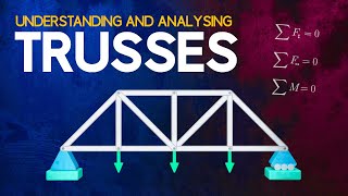
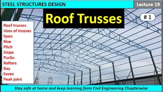
Cables and trusses are 2D or 3D structures composed of an assemblage of simple one-dimensional components which transfer only axial forces along their axis. Cables can carry only tensile forces, trusses can carry tensile and compressive forces. Cables tend to be flexible, and hence, they tend to oscillate and therefore must be stiffened. Trusses are extensively used for bridges, long span roofs, electric towers, and space structures.
Detailed Explanation
This chunk introduces the concept of trusses, explaining that they are structural frameworks made of simple components that mostly transfer forces along their length (axial forces). Cables are only able to hold tension and are flexible, which can lead to oscillation. Trusses, on the other hand, can handle both tension and compression, making them suitable for various heavy-duty constructions such as bridges and roofs.
Examples & Analogies
Imagine a hammock (representing a cable) that only supports you when it is pulled tight, versus a bridge (representing a truss) that can support not only your weight (tension) but also the weight of a truck (compression) as it moves across, showing how trusses are robust in various applications.
Assumptions in Truss Analysis
Chapter 2 of 7
🔒 Unlock Audio Chapter
Sign up and enroll to access the full audio experience
Chapter Content
For trusses, it is assumed that 1. Bars are pin-connected. 2. Joints are frictionless hinges. 3. Loads are applied at the joints only.
Detailed Explanation
This chunk outlines the basic assumptions made when analyzing trusses. First, the bars that make up the truss are assumed to be pin-connected, which allows them to rotate freely at the joints. Second, the joints are treated as frictionless hinges, meaning they do not resist rotation or movement. Lastly, it's assumed that external loads are only applied at these joints, simplifying the calculation of forces.
Examples & Analogies
Think of a mobile hanging from the ceiling where each part can freely rotate at the joints (like pin connections), allowing the mobile to sway gently without resistance. This illustrates how the assumptions about connection types in trusses help simplify calculations in engineering.
Types of Forces in Trusses
Chapter 3 of 7
🔒 Unlock Audio Chapter
Sign up and enroll to access the full audio experience
Chapter Content
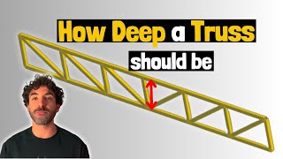
A truss would typically be composed of triangular elements with the bars on the upper chord under compression and those along the lower chord under tension. Depending on the orientation of the diagonals, they can be under either tension or compression.
Detailed Explanation
In truss structures, the design typically consists of triangular shapes which help distribute forces evenly. The upper bars or chords experience compression, meaning they are being 'pushed together', while the lower chords are under tension, 'pulling apart'. The diagonal bars can either be under tension or compression depending on their orientation and load direction, which is key in maintaining the integrity of the truss.
Examples & Analogies
Consider a set of ropes supporting a hanging piece of art. The ropes at the top (upper chord) want to push down or compress, while those at the bottom (lower chord) are stretched or in tension, serving as an example of how trusses balance forces akin to a simple hanging art installation.
Types of Trusses
Chapter 4 of 7
🔒 Unlock Audio Chapter
Sign up and enroll to access the full audio experience
Chapter Content
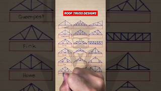
In a Pratt truss, the diagonal members are under tension, while in a Howe truss, they are in compression. The Pratt design is an excellent choice for steel as its slender members under tension are not prone to buckling. The vertical members are less likely to buckle because they are shorter. On the other hand, the Howe truss is often preferred for heavy timber trusses.
Detailed Explanation
This chunk describes different types of trusses. The Pratt truss has diagonal members that deal with tension forces, making it ideal for lightweight structures like steel frameworks that resist buckling. Conversely, the Howe truss has diagonal members that handle compression, making it suitable for heavier materials like timber. The design choice affects how forces are managed in construction.
Examples & Analogies
Think of a bicycle brake system. The cables tightening to stop the bike represent tension (like in a Pratt truss), while the metal rods that compress to apply brakes are akin to the Howe truss. The way forces are managed differently in each component reflects the design choices made in building trusses.
Static Determinacy and Stability of Trusses
Chapter 5 of 7
🔒 Unlock Audio Chapter
Sign up and enroll to access the full audio experience
Chapter Content
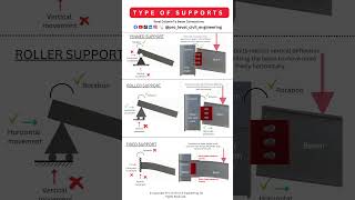
Trusses are statically determinate when all the bar forces can be determined from the equations of statics alone. Otherwise, the truss is statically indeterminate. A truss may be statically/externally determinate or indeterminate with respect to the reactions (more than 3 or 6 reactions in 2D or 3D problems respectively).
Detailed Explanation
This section clarifies the conditions under which a truss can be statically determined or not. A statically determinate truss allows all internal forces to be found using basic static equations, while an indeterminate truss does not, making the calculations more complex. The number of external reactions involved also determines stability and whether it’s externally or internally determined.
Examples & Analogies
Consider a simple puzzle. If you have enough pieces to solve it (statically determinate), you can complete it without guessing. However, if there are extra pieces or missing edges (statically indeterminate), it becomes challenging, similar to how knowing the reaction forces in a truss helps or hinders analysis.
Equations of Equilibrium for Trusses
Chapter 6 of 7
🔒 Unlock Audio Chapter
Sign up and enroll to access the full audio experience
Chapter Content
For 2D trusses, the external equations of equilibrium which can be used to determine the reactions are ΣF_x = 0, ΣF_y = 0 and ΣM = 0. For 3D trusses, the available equations are ΣF_x = 0, ΣF_y = 0, ΣF_z = 0 and ΣM_x = 0, ΣM_y = 0, ΣM_z = 0.
Detailed Explanation
This chunk explains the mathematical foundation for analyzing trusses. For 2D structures, two force equations along the X and Y axes, and one moment equation are essential for finding reactions. For 3D structures, three force equations and three moment equations are necessary. Knowing how to apply these equations allows engineers to analyze complex structures accurately.
Examples & Analogies
Imagine balancing a seesaw. You need to know how much weight is on each side (similar to ΣF), and you need to understand how far they are from the pivot (like ΣM) to ensure balance. This balancing act mirrors how engineers use equilibrium equations to maintain stability in trusses.
Sign Convention in Truss Analysis
Chapter 7 of 7
🔒 Unlock Audio Chapter
Sign up and enroll to access the full audio experience
Chapter Content
In truss analysis, there is no sign convention. A member is assumed to be under tension (or compression). If after analysis, the force is found to be negative, then this would imply that the wrong assumption was made, and that the member should have been under compression (or tension).
Detailed Explanation
This section highlights how assumptions play a role in truss analysis. Initially, engineers assume whether a member is in tension or compression without a strict sign convention. After performing calculations, if a negative value emerges, it indicates the assumption was incorrect, requiring adjustments to how forces are viewed.
Examples & Analogies
Think of a game of 'guess what’s in the box'. If you believe it’s a soft toy (tension) but it turns out to be a rock (compression), your initial guess was wrong. Similarly, in truss analysis, incorrect assumptions lead to a reevaluation of forces acting within the structure.
Key Concepts
-
Trusses: Structures composed of triangular elements transferring forces.
-
Tension and Compression: Fundamental forces experienced by truss members.
-
Determinacy and Stability: Configurations affecting analysis and design.
Examples & Applications
Example 1: Analyze a simple truss using the method of joints to find internal forces.
Example 2: Compare the Pratt and Howe truss types based on member stress distribution.
Memory Aids
Interactive tools to help you remember key concepts
Rhymes
For a truss that stays in place, pin-connected is the case. Load at the joints should apply, in this way, the truss will fly!
Stories
Imagine a group of triangles working together, each holding hands at their corners. They only load where they meet! This way, they can withstand strength like no other, always balanced by forces of compression and tension.
Memory Tools
Remember 'P-F-J': Pin-connected, Frictionless joint, Load at joints — critical aspects of trusses.
Acronyms
For determination of trusses
**'M+R=2J'** refers to the relationship of members
reactions
and joints.
Flash Cards
Glossary
- Truss
A structure defined by its interconnected members that carry axial forces, both tensile and compressive.
- Axial Force
A force that acts along the length of a member in a truss structure.
- Statically Determinate
A condition where all internal forces can be determined using the equations of static equilibrium alone.
- Statically Indeterminate
A condition where additional information is required beyond equilibrium equations to determine internal forces.
- Equilibrium
The state in which the sum of forces and moments acting on a body equals zero.
- Method of Joints
A technique used in truss analysis that involves analyzing the forces at each joint independently to calculate internal forces.
Reference links
Supplementary resources to enhance your learning experience.