
RLC Circuits - Series and Parallel Circuits
Interactive Audio Lesson
Listen to a student-teacher conversation explaining the topic in a relatable way.
Introduction to RLC Circuits
🔒 Unlock Audio Lesson
Sign up and enroll to listen to this audio lesson

Today, we will learn about RLC circuits, which are made up of resistors, inductors, and capacitors. They can be arranged in series or parallel. Can anyone tell me what these components do?

Resistors limit current!

Inductors store energy in a magnetic field!

Capacitors store energy in an electric field!
Great! So RLC circuits can store and exchange energy. One significant aspect is their ability to resonate. What do you think resonance means?

Isn't it when the circuit responds strongly at a certain frequency?
Exactly! Resonance occurs at the resonant frequency, where circuits exhibit maximum current or voltage. 🌟 Remember: *RLC - Resonance, Limiting, Control*!
Series RLC Circuits
🔒 Unlock Audio Lesson
Sign up and enroll to listen to this audio lesson

In a series RLC circuit, components are connected one after another. Can anyone tell me how to calculate the total impedance?
I remember it involves resistance and reactance!
Correct! The total impedance is given by Z = R + j(ωL - 1/ωC). This shows how resistance and reactance work together. What happens at resonance?
The impedance is at a minimum, right?
Yes indeed! At resonance, the current is maximized. To remember this, think *Resonance = Reduced Impedance = Ramp Up Current*! 📈
Parallel RLC Circuits
🔒 Unlock Audio Lesson
Sign up and enroll to listen to this audio lesson
Now, let’s look at parallel RLC circuits. Who can explain how components are connected?
They are connected across the same voltage source, so they share the same voltage!
Exactly! This configuration leads to different impedance behavior. Can you remember the formula for total admittance?
Y = 1/R + 1/jωL + jωC!
Great job! In parallel circuits, we can also set them up as bandstop filters. Just remember, *Parallel = Peak Yields Lower Impedance*! 🔄
Applications of RLC Circuits
🔒 Unlock Audio Lesson
Sign up and enroll to listen to this audio lesson
RLC circuits find many applications. Can you think of where we might use them?
In radio receivers to tune into specific frequencies!
And in power supplies to filter out noise!
Absolutely! For both tuning and filtering, RLC circuits play a crucial role. One way to remember is *Tune for Sound, Filter out Noise*! 🎶
Introduction & Overview
Read summaries of the section's main ideas at different levels of detail.
Quick Overview
Standard
RLC circuits consist of resistors, inductors, and capacitors arranged in series or parallel. The section details the impedance analysis, resonance conditions, time domain response, and practical applications. It also illustrates how these circuits can function as filters and oscillators.
Detailed
In-Depth Overview of RLC Circuits
RLC circuits are electrical circuits composed of resistors (R), inductors (L), and capacitors (C), configured either in series or parallel arrangements. These circuits are fundamental in electronics because they exhibit unique behaviors, including resonance, energy storage, and filtering properties.
Key Characteristics
- Resonance: RLC circuits resonate at specific frequencies, allowing them to select desired signals while filtering out others.
- Energy Exchange: Inductors and capacitors can store and release energy, contributing to the circuit's oscillatory behavior.
Series RLC Circuits
In series configurations, the total impedance
evaluates to
Z = R + j(ωL - 1/ωC). The behavior varies significantly with frequency, especially at the resonant frequency ω0 = 1/√(LC), where current is maximized. The circuit's quality factor (Q) indicates bandwidth and resonance sharpness.
Parallel RLC Circuits
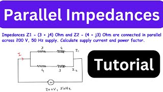
Parallel configurations exhibit total admittance, combining components inversely. They too resonate at the same frequency and can be used to design bandstop filters. The quality factor in parallel circuits highlights their response to resonant frequencies, guiding design applications.
Practical Applications
RLC circuits find use in tuned circuits for radio receivers and noise filtering systems, showcasing their essential role in modern electronics.
Youtube Videos
Audio Book
Dive deep into the subject with an immersive audiobook experience.
Introduction to RLC Circuits
Chapter 1 of 6
🔒 Unlock Audio Chapter
Sign up and enroll to access the full audio experience
Chapter Content
2.1 Introduction to RLC Circuits
- Definition:
- Circuits containing Resistors (R), Inductors (L), and Capacitors (C) in series/parallel configurations
- Key Characteristics:
- Exhibit resonance behavior
- Can act as filters or oscillators
- Store and exchange energy between L and C components
Detailed Explanation
RLC circuits are electrical circuits that contain resistors, inductors, and capacitors. These three components can be arranged in series, where they are connected one after the other, or in parallel, where they are connected beside each other. One important feature of RLC circuits is their ability to resonate at specific frequencies. This means that they can selectively respond to certain frequency signals while filtering others. Additionally, these circuits are capable of storing energy; inductors store it in the magnetic field, while capacitors store it in the electric field.
Examples & Analogies
Consider a swing in a playground. Just as the swing has a natural frequency at which it oscillates smoothly, RLC circuits have specific frequencies where they resonate. If you push the swing at its natural frequency, it goes higher, just like an RLC circuit can amplify certain signals.
Series RLC Circuits Overview
Chapter 2 of 6
🔒 Unlock Audio Chapter
Sign up and enroll to access the full audio experience
Chapter Content
2.2 Series RLC Circuits
2.2.1 Basic Configuration
V_in ──R──L──C──┐
│
GND
2.2.2 Impedance Analysis
- Total Impedance (Z):
\[
Z = R + jωL + \frac{1}{jωC} = R + j\left(ωL - \frac{1}{ωC}\right)
\] - Magnitude and Phase:
\[
|Z| = \sqrt{R^2 + \left(ωL - \frac{1}{ωC}\right)^2}
\]
\[
θ = \tan^{-1}\left(\frac{ωL - 1/ωC}{R}\right)
\]
Detailed Explanation
In a series RLC circuit, the components are connected linearly from a voltage source to ground. The total impedance, which is the opposition to current flow, combines resistance (R), inductive reactance (representing the inductor L, denoted as jωL where j is the imaginary unit), and capacitive reactance (from the capacitor C, noted as 1/jωC). The total impedance can be calculated using the formula provided. Furthermore, we can analyze the magnitude of the impedance and its phase angle to understand how the circuit behaves with alternating current (AC).
Examples & Analogies
Imagine a water hose where the normal flow (current) encounters various restrictions (impedances). The resistance is like a kinks in the hose, which slows the water flow greatly. The reactance from the inductor and capacitor can be thought of as valves that open and close, altering how much water can flow depending on how much is being pushed at that moment.
Resonance in Series RLC Circuits
Chapter 3 of 6
🔒 Unlock Audio Chapter
Sign up and enroll to access the full audio experience
Chapter Content
2.2.3 Resonance Conditions
- Resonant Frequency:
\[
ω_0 = \frac{1}{\sqrt{LC}}
\] - Quality Factor (Q):
\[
Q = \frac{ω_0L}{R} = \frac{1}{ω_0CR}
\] - Bandwidth:
\[
BW = \frac{ω_0}{Q}
\]
Detailed Explanation
The resonant frequency (ω₀) is the frequency at which a series RLC circuit produces maximum voltage across the components. This is derived from the values of inductance (L) and capacitance (C) using the formula given. The quality factor (Q) is a measure of how 'sharp' the resonance is; higher Q means a better selection of frequency with less bandwidth. Bandwidth signifies the range of frequencies around the resonant frequency where the circuit can effectively operate.
Examples & Analogies
Think of tuning a guitar. Each string has a specific pitch (resonant frequency) that can resonate when you pluck it. If the string is tightly wound (high Q), you get a clear note with very little variation (narrow bandwidth), but if it's loosely wound (low Q), the note may sound muted and cover a wider pitch range (wider bandwidth).
Parallel RLC Circuits Overview
Chapter 4 of 6
🔒 Unlock Audio Chapter
Sign up and enroll to access the full audio experience
Chapter Content
2.3 Parallel RLC Circuits
2.3.1 Basic Configuration
┌─R─┐
V_in ─┼─L─┼─┐
└─C─┘ │
GND
Detailed Explanation
In parallel RLC circuits, the components are connected side by side rather than in a line. Each component experiences the same voltage from the source, but the current can divide across the resistors, capacitors, and inductors based on their respective impedances.
Examples & Analogies
Think of a multi-lane highway where all cars (current) can take different lanes (paths) but are traveling at the same speed (voltage). Depending on conditions, more cars may choose a certain lane over another, just like how current flows through different components based on their individual properties.
Admittance Analysis in Parallel RLC Circuits
Chapter 5 of 6
🔒 Unlock Audio Chapter
Sign up and enroll to access the full audio experience
Chapter Content
2.3.2 Admittance Analysis
- Total Admittance (Y):
\[
Y = \frac{1}{R} + \frac{1}{jωL} + jωC
\] - Magnitude and Phase:
\[
|Y| = \sqrt{\left(\frac{1}{R}\right)^2 + \left(ωC - \frac{1}{ωL}\right)^2}
\]
Detailed Explanation
In parallel circuits, we analyze the total admittance (Y), which indicates how easily current can flow through the circuit components. Admittance is the inverse of impedance. Just like how we summed the impedances in series, we sum the admittances in parallel to get the total admittance. The calculation provided allows us to understand both the magnitude and the phase characteristics of the current flow in the circuit.
Examples & Analogies
Imagine a group of friends each working at different jobs (the components) but all contributing to a joint project. Each friend has different skills (resistance, inductance, capacitance), and when you combine their efforts (admittance), you can see how efficiently your group (circuit) can complete the project (current flow).
Resonance in Parallel RLC Circuits
Chapter 6 of 6
🔒 Unlock Audio Chapter
Sign up and enroll to access the full audio experience
Chapter Content
2.3.3 Resonance Conditions
- Resonant Frequency (same as series):
\[
ω_0 = \frac{1}{\sqrt{LC}}
\] - Quality Factor:
\[
Q = R\sqrt{\frac{C}{L}}
\]
Detailed Explanation
Similar to series RLC circuits, parallel RLC circuits also exhibit resonance at the same frequency determined by the inductance (L) and capacitance (C). However, the quality factor (Q) differs based on the resistance (R) and the ratio of capacitance to inductance. This affects how sharp or pronounced the resonance effect is when the circuit is in operation.
Examples & Analogies
Returning to the example of a guitar tuning, while each string (signal) vibrates freely, the thickness and tension of the string (resistance, capacitance, inductance) will affect how clearly it plays a note (resonance effect) when strummed. In this case, thicker strings may produce deeper, looser notes than lighter ones, just as the components influence performance in the circuit.
Key Concepts
-
Resonance: The phenomenon where circuits are at their most responsive at specific frequencies.
-
Impedance: The combined effect of resistance and reactance in a circuit.
-
Quality Factor (Q): A measure of how underdamped a circuit is, affecting its performance at resonance.
-
Bandwidth: The range of frequencies that a circuit can effectively handle.
Examples & Applications
A radio receiver's tuning circuit is a practical application of a series RLC circuit.
A parallel RLC circuit can serve as a noise filter for power supplies.
Memory Aids
Interactive tools to help you remember key concepts
Rhymes
RLC circuits are neat, they store energy sweet, at resonant frequency, they can't be beat!
Stories
Imagine RLC as a dance team: Resistor keeps everyone steady, Inductor leads the spins, while Capacitor catches the energy. Together, they create a harmonious resonance!
Memory Tools
RLC = 'Resonance, Limit, Control' helps remember the function of each component.
Acronyms
Remember RLC using 'Real Love Connection' to highlight the connective role of the components.
Flash Cards
Glossary
- RLC Circuit
A circuit that contains a resistor, inductor, and capacitor, which can be arranged in series or parallel.
- Impedance (Z)
The total opposition that a circuit offers to the flow of alternating current, comprising resistance and reactance.
- Admittance (Y)
The measure of how easily a circuit allows current to flow, the reciprocal of impedance.
- Resonance
The condition in which a circuit naturally oscillates at greater amplitude at its resonant frequency.
- Quality Factor (Q)
A dimensionless parameter that describes how underdamped an oscillator or resonator is, related to its bandwidth.
- Bandwidth (BW)
The range of frequencies over which a circuit operates effectively.
Reference links
Supplementary resources to enhance your learning experience.