
Example (50Ω → 75Ω Match)
Interactive Audio Lesson
Listen to a student-teacher conversation explaining the topic in a relatable way.
Introduction to Impedance Matching
🔒 Unlock Audio Lesson
Sign up and enroll to listen to this audio lesson

Today, we are going to talk about impedance matching. Can anyone tell me why impedance matching is important?

Is it to ensure that we get the maximum power transfer?
Exactly! Good job! We want to eliminate reflections to maximize power transfer between the source and load.

What happens when there are reflections?
Reflections can cause interference and reduce the efficiency of the circuit. This is why we use tools like the Smith Chart to visualize and design matching networks.

And how do we know what components to use?
That’s what we’ll explore today through an example: matching a 50Ω source to a 75Ω load.
Explaining the Smith Chart
🔒 Unlock Audio Lesson
Sign up and enroll to listen to this audio lesson

Let’s explore the Smith Chart. Can anyone explain how the Smith Chart helps in impedance matching?

It allows us to visualize impedance and reactance on a single plot, right?
Correct! It simplifies the process of finding matching components. Now, for our example, we need to plot the impedance of the load.
How do we initiate this process?
First, we normalize the impedance of our load—a 75Ω load relative to our 50Ω source.
Calculating Component Values
🔒 Unlock Audio Lesson
Sign up and enroll to listen to this audio lesson
Now that we have our normalized load impedance, let’s calculate the matching components. We will use a series inductor and a shunt capacitor. Who can tell me the desired values?
The series inductor should be 6.5 nH, and the shunt capacitor should be 2.1 pF at 1GHz.
Excellent! Let’s discuss why these values are needed for our matching network. How do they affect impedance?
I think the inductor increases reactance while the capacitor decreases it, helping us match the impedance.
Great understanding! So these components will help us reach the desired impedance for optimal power transfer.
Summary and Application
🔒 Unlock Audio Lesson
Sign up and enroll to listen to this audio lesson
In summary, we discussed how to match a 50Ω source to a 75Ω load using a Smith Chart. Why is it crucial to find the right components?
To ensure maximum power is transferred and to avoid losses due to reflections!
Exactly! Remember, impedance matching is essential in many electronic applications, especially in RF design.
Thanks for the explanations! I feel more confident about using the Smith Chart now.
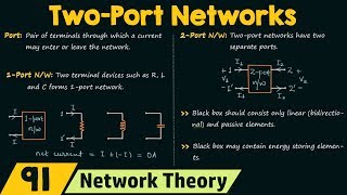
Introduction & Overview
Read summaries of the section's main ideas at different levels of detail.
Quick Overview
Standard
The section illustrates a real-world application where a series inductor and shunt capacitor are utilized to match a 50Ω source impedance to a 75Ω load at 1GHz. It emphasizes the importance of proper component selection in impedance matching.
Detailed
Example of Impedance Matching Using Smith Chart
In this section, we explore the impedance matching process using a Smith Chart, specifically transforming a 50Ω source to successfully match a 75Ω load. The Smith Chart allows engineers to visualize complex impedances and easily determine the necessary components for matching.
The example given utilizes two components: a series inductor and a shunt capacitor. At a frequency of 1GHz, the required values are calculated as follows:
- Series Inductor (L): 6.5 nH
- Shunt Capacitor (C): 2.1 pF
These components adjust the impedance at the load to ensure that reflections are minimized and maximum power transfer occurs. This process demonstrates the practical application of theoretical concepts in real-world scenarios.
Youtube Videos


Audio Book
Dive deep into the subject with an immersive audiobook experience.
Solution Overview
Chapter 1 of 3
🔒 Unlock Audio Chapter
Sign up and enroll to access the full audio experience
Chapter Content
- Solution:
Detailed Explanation
This chunk serves as a heading for the solution of the impedance matching example, specifically a match from 50Ω to 75Ω. In matching network design, it's important to express the solutions clearly before diving into the specific components needed for the match.
Examples & Analogies
Imagine you're trying to connect a standard headphone plug (which may have an impedance around 50Ω) to a more specialized audio equipment input that is designed for 75Ω. The goal is to ensure that the audio signal can be transmitted efficiently without losing quality.
Series Inductor Calculation
Chapter 2 of 3
🔒 Unlock Audio Chapter
Sign up and enroll to access the full audio experience
Chapter Content
- Series Inductor:
L = 6.5 ext{nH}at 1GHz.
Detailed Explanation
The solution involves using a series inductor to transform the impedance from 50Ω to the target impedance of 75Ω. At a frequency of 1GHz, the calculated inductance needed to achieve this match is 6.5 nanohenries (nH). The inductor increases the reactance, which is essential for achieving a better impedance match at the specified frequency.
Examples & Analogies
Think of adding a series inductor like adding a weight to one side of a seesaw, which helps balance it out when the other side is heavier. Here, the inductor compensates for the lower impedance of the source to better match the load.
Shunt Capacitor Calculation
Chapter 3 of 3
🔒 Unlock Audio Chapter
Sign up and enroll to access the full audio experience
Chapter Content
- Shunt Capacitor:
C = 2.1 ext{pF}at 1GHz.
Detailed Explanation
In addition to the series inductor, a shunt capacitor is also needed in this design. The calculated capacitance required is 2.1 picofarads (pF) at the same frequency of 1GHz. The shunt capacitor provides a path to ground for higher-frequency signals, allowing for improved impedance matching and minimization of reflection loss.
Examples & Analogies
Using a shunt capacitor is like providing a shortcut for water in a plumbing system where the main pipe is too small. The capacitor allows excess charges (like excess water) to be grounded, improving the overall flow (or signal integrity) through the system.
Key Concepts
-
Impedance Matching: The technique to optimize power transfer by minimizing reflections.
-
Smith Chart: A visual aid used to find reactance and impedance values for matching circuits.
-
Series Inductor: Used to add inductive reactance to the circuit.
-
Shunt Capacitor: Used to add capacitive reactance to the circuit.
Examples & Applications
Matching a 50Ω source to a 75Ω load using a series inductor of 6.5 nH and shunt capacitor of 2.1 pF at 1GHz.
Memory Aids
Interactive tools to help you remember key concepts
Rhymes
For a perfect match, don't forget to hatch, A series inductor is worth the catch, A shunt capacitor will help in the patch.
Stories
Imagine two friends, Impedance and Matching, they meet at a party. Impedance is wearing a 50Ω badge and is looking for its perfect match of 75Ω. They realize with a series inductor and a shunt capacitor, they can finally get together without any reflections.
Memory Tools
I M S: Impedance Matching with Series inductors and a Shunt capacitor.
Acronyms
AC
for series Inductor and C for shunt Capacitor - always remember your matching duo!
Flash Cards
Glossary
- Smith Chart
A graphical tool used for impedance matching and analyzing complex impedances in radio frequency applications.
- Impedance Matching
The process of making the impedance of the load equal to the impedance of the source to maximize power transfer.
- Normalized Impedance
The impedance scaled with a reference value, typically the characteristic impedance of the system.
- Reactance
The component of impedance that accounts for the energy storage in capacitors and inductors.
- Series Inductor
An inductor connected in series with the load to introduce inductive reactance.
- Shunt Capacitor
A capacitor connected in parallel with the load to introduce capacitive reactance.
Reference links
Supplementary resources to enhance your learning experience.