
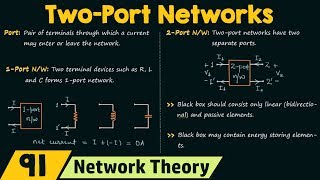
Pi (π) and T-Networks
Interactive Audio Lesson
Listen to a student-teacher conversation explaining the topic in a relatable way.
Introduction to Pi-Networks
🔒 Unlock Audio Lesson
Sign up and enroll to listen to this audio lesson

Today, we're going to look at Pi-networks. Who can tell me what they know about Pi-networks and where they might be used?

I think Pi-networks are related to impedance matching. They're used in amplifiers, right?
Exactly! Pi-networks are often employed in RF applications for high-Q matching. They consist of capacitors and inductors arranged in a way to minimize reflections. Can anyone describe the basic structure of a Pi-network?

It's like a 'π' shape, right? With a capacitor at the input and output, and sometimes an inductor in the middle?
That's correct! The basic representation is an input capacitor that connects to two shunt components, ensuring a smooth matching process. Remember, Pi-networks are particularly effective in RF amplifiers due to their high quality factor. Can anyone give me a mnemonic to remember the components involved?

How about 'Capacitor in, Inductor out, Matching devout'?
Great memory aid! Let’s move on and talk about T-networks.
Understanding T-Networks
🔒 Unlock Audio Lesson
Sign up and enroll to listen to this audio lesson

Now, let's dive into T-networks. What do you remember about the structure of T-networks?

I think T-networks use inductors and a capacitor, correct? They're more suited for low-impedance loads.
That's right! The typical configuration includes one series inductor and one shunt capacitor. This allows T-networks to perform well with low impedances while providing an efficient path for current. Why is that advantageous?
Because it can handle higher currents without significant loss?
Absolutely! More importantly, T-networks can also aid in transforming the impedance, making them versatile in circuit design. Can anyone think of a practical application for T-networks?
Maybe in radio transmitters where low impedance is common?
Exactly right! Understanding both Pi and T-network configurations can significantly enhance your designs. Let's summarize today's key points: Pi-networks are great for high-Q matching in RF amplifiers, while T-networks shine with low-impedance loads.
Comparing Pi and T-Networks
🔒 Unlock Audio Lesson
Sign up and enroll to listen to this audio lesson
Before we finish up today, let's analyze the differences between Pi and T-networks. What are some key takeaways?
Pi-networks are better for high-Q applications, while T-networks help with low-impedance scenarios.
Right! You can use both for impedance matching, but their applications differ based on the load impedance. Can you think of a scenario where you might choose one over the other?
If I have a low-impedance load in an RF transmission line, I'd go for a T-network.
That's a perfect example! Understanding when to use each network can really improve circuit performance. Let's wrap up with a quick review of the key concepts discussed today regarding both network types and their structures.
Introduction & Overview
Read summaries of the section's main ideas at different levels of detail.
Quick Overview
Standard
The Pi and T-networks are common topologies used to achieve impedance matching in RF applications. Pi-networks are often employed for high-Q matching, making them suitable for RF amplifiers, while T-networks are preferred for low-impedance loads. Understanding their configuration and application is crucial for optimizing power transfer and minimizing reflected waves.
Detailed
Detailed Summary
In this section, we explore two important network topologies used in impedance matching: the Pi (π) network and the T-network. Both configurations are pivotal in ensuring maximum power transfer and minimizing signal reflections in radio frequency (RF) applications.
1. Pi-Network
The Pi-network topology consists of a series capacitor with two shunt components. It is specifically designed to meet the needs of high-Q matching applications, such as RF amplifiers. In practical terms, this network can be represented as:
Source ──┬── C1 ──┬── Load
│         │
L         C2
│         │
GND       GND
The arrangement allows for fine-tuning of impedance to ensure a match between the source and load throughout the desired frequency range.
2. T-Network
Conversely, the T-network configuration is composed of a series inductor with a shunt capacitor, ideal for low-impedance loads. This structure can handle higher current levels more efficiently than the Pi-network:
Source ── L1 ──┬── L2 ── Load
│
C
│
GND
The T-network thus provides an effective means to match low-impedance loads while maintaining performance over a range of frequencies.
Understanding both network types is essential for electrical engineers and technologists involved in RF design and impedance matching.
Youtube Videos


Audio Book
Dive deep into the subject with an immersive audiobook experience.
Overview of Pi-Networks
Chapter 1 of 2
🔒 Unlock Audio Chapter
Sign up and enroll to access the full audio experience
Chapter Content
Pi-Network:
Source ──┬── C1 ──┬── Load
│ │
L C2
│ │
GND GND
- Used for high-Q matching (e.g., RF amplifiers).
Detailed Explanation
A Pi-Network is a type of matching network usually depicted with its components arranged in a 'π' shape. In this configuration, the source connects to the network through a capacitor (C1), which is followed by an inductor (L) and then another capacitor (C2) connecting to the load. This structure allows the network to exhibit high quality (high-Q) matching, making it suitable for applications like RF amplifiers that require precise impedance matching to maximize power transfer and minimize signal reflections.
Examples & Analogies
Think of it like tuning a musical instrument: you adjust the tension on the strings (the components of the Pi-Network) until the instrument produces a perfect sound (maximum power transfer). Just as musicians aim for harmony, an RF amplifier uses this network to achieve optimal performance.
Overview of T-Networks
Chapter 2 of 2
🔒 Unlock Audio Chapter
Sign up and enroll to access the full audio experience
Chapter Content
T-Network:
Source ── L1 ──┬── L2 ── Load
│
C
│
GND
- Better for low-impedance loads.
Detailed Explanation
A T-Network is another type of matching network, laid out in a 'T' shape. In this setup, the source is connected to an inductor (L1), which branches off to a load through another inductor (L2) while a capacitor (C) connects from the center of the 'T' to ground. This topology is particularly effective when connecting to low-impedance loads, as it can transform and balance impedances more efficiently than other configurations.
Examples & Analogies
Imagine a road (the T-Network) leading toward a neighborhood (the load). The road forks off, allowing cars from a main highway (the source) to easily reach various houses (the load). The connector (the capacitor) helps manage the flow, ensuring that the vehicles get to their destination smoothly, similar to transforming impedances in electronic circuits.
Key Concepts
-
Pi-Network: A topology used for high-Q matching, consisting of capacitors and inductors arranged in a 'π' structure.
-
T-Network: A circuit design featuring series inductors and shunt capacitors for effective low-impedance load matching.
-
Impedance Matching: The practice of minimizing reflections to optimize power transfer in circuits.
Examples & Applications
Using a Pi-network to match an RF amplifier's output to a 50Ω load for optimal performance.
Designing a T-network to efficiently match a low-impedance load, such as an antenna, to a transmitter.
Memory Aids
Interactive tools to help you remember key concepts
Rhymes
In networks Pi makes the match, for RF amps that catch, T works low and can dispatch!
Stories
Imagine two engineers: one building a high-Q amplifier with a Pi-network, ensuring pristine signals, while the other is matching low-impedance loads using a T-network, ensuring all currents flow smoothly.
Memory Tools
P.I.E (Pi Is Essential for high-Q) helps remember that Pi-networks excel in high-Q applications while T-networks tackle low-load-impedances.
Acronyms
PIT (Pi Impedance Transformers) signifies that Pi-networks transform impedances in high-Q scenarios.
Flash Cards
Glossary
- PiNetwork
A network topology involving capacitors and inductors arranged to create a 'π' shape for high-Q matching applications.
- TNetwork
A network topology that uses series inductors and shunt capacitors, suitable for matching low-impedance loads.
- HighQ Matching
Impedance matching that ensures low losses and high efficiency at specific frequencies.
- Impedance Matching
A technique used to maximize power transfer between a source and load by minimizing reflections.
Reference links
Supplementary resources to enhance your learning experience.